Electrolyte plasma polishing machine

A polishing machine and plasma technology, which is applied in the field of polishing machines, can solve the problems of large size and difficult handling of polishing machines, and achieve the effects of good operation, simple and easy installation process, and reduced volume

Inactive Publication Date: 2012-09-12
HARBIN INST OF TECH
View PDF6 Cites 14 Cited by
  • Summary
  • Abstract
  • Description
  • Claims
  • Application Information

AI Technical Summary

Problems solved by technology

[0003] The purpose of the present invention is to provide an electrolyte plasma polishing machine to solve the problem that the current polishing machine has a large volume and is difficult to carry

Method used


Image

  • Electrolyte plasma polishing machine
  • Electrolyte plasma polishing machine
  • Electrolyte plasma polishing machine

Examples


specific Embodiment approach 1

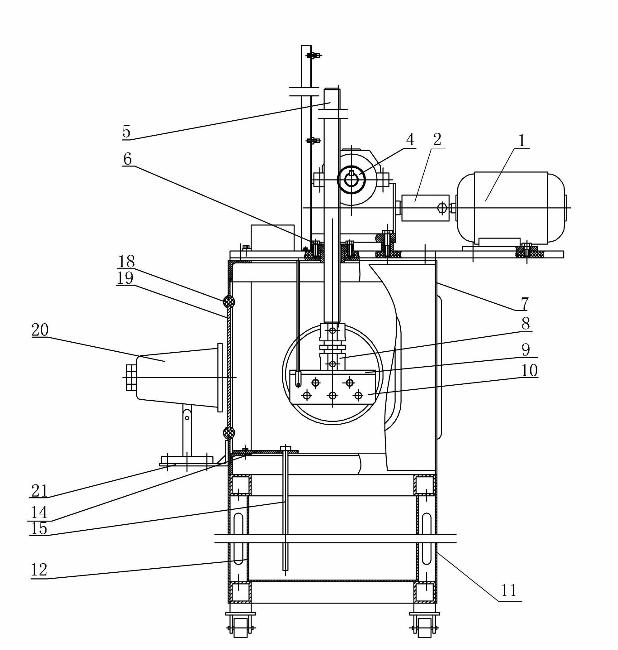
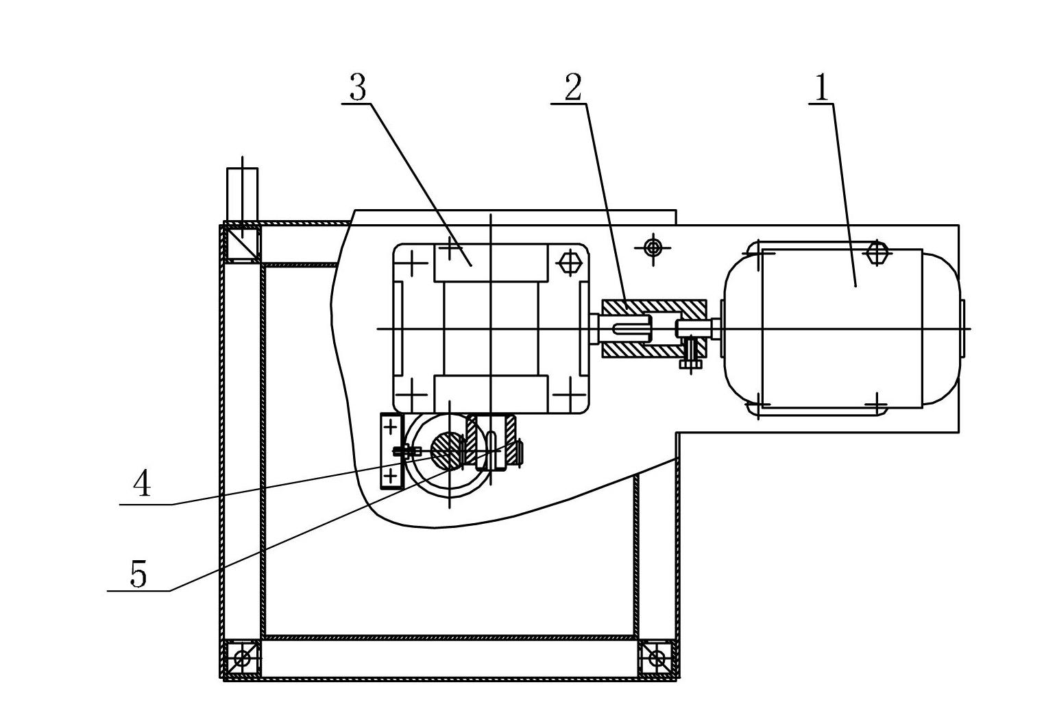
[0007] Specific implementation mode one: combine Figure 1-Figure 3 Describe this embodiment, the polishing machine of this embodiment includes motor 1, coupling 2, speed reducer 3, gear 4, rack 5, guide sleeve 6, upper box 7, insulator 8, connecting plate 9, anode 10, lower Box 11, working box 12, heater 13, heater rack 14, condensation pipe 15 and pipe joint 22, the output shaft of motor 1 is connected with the input shaft of reducer 3 through coupling 2, the output shaft of reducer 3 A gear 4 is mounted on the top, and the gear 4 meshes with the rack 5. One end of the rack 5 passes through the guide sleeve 6 and is installed in the upper box 7 and connected with the insulator 8. The insulator 8 is connected with the anode 10 through the connecting plate 9, and the guide sleeve 6 is fixed. Installed on the top of the upper box 7, the upper box 7 is installed on the lower box 11 and the two are connected, the lower box 11 is provided with a working box 12 with polishing fluid...

specific Embodiment approach 2

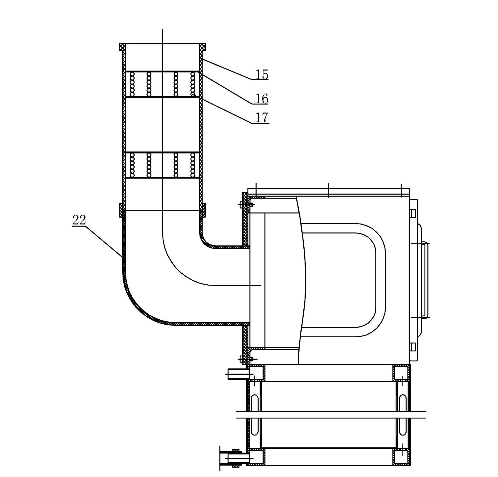
[0008] Specific implementation mode two: combination image 3 Illustrate this embodiment, the polishing machine of this embodiment also comprises water spray sheet 16 and water spray ball 17, and described polishing machine also comprises multiple groups of water spray sheet 16 and multiple groups of water spray ball 17, and multiple groups of water spray are housed in condenser tube 15 Sheet 16, the number of each group of water spray sheets 16 is 2, each group of water spray sheets 16 is provided with multiple groups of water spray balls 17, the water vapor generated in the polishing process is cooled when passing through the water spray balls 17, becomes water, and flows back into the workbox 12. Other implementation manners are the same as the specific implementation manner 1.

specific Embodiment approach 3

[0009] Specific implementation mode three: combination figure 1 Describe this embodiment, the polishing machine of this embodiment also comprises six rubber strips 18 and three glass windows 19, glass windows 19 are housed on the three side walls of upper case 7, and each glass window 19 is provided with two rubber strips Article 18, the main purpose of this portable device is to display and process small-volume parts, and three observation windows are added to facilitate the display of the polishing process. Other implementation modes are the same as the specific implementation mode 1 or 2.


PUM


Abstract

The invention discloses an electrolyte plasma polishing machine, which relates to a polisher and is used for solving the problem of difficulty in carrying the conventional large-sized polishing machine. An output shaft of a motor is in transmission connection with an input shaft of a speed reducer through a shaft coupling; a gear is arranged on an output shaft of the speed reducer, and is meshed with a rack; one end of the rack passes through a guide sleeve, is arranged in an upper box, and is connected with an insulator; the insulator is connected with an anode through a connecting plate; the guide sleeve is fixedly arranged on the top of the upper box; the upper box is arranged on and is communicated with the lower box; a working box filled with a polishing liquid is arranged in the lower box, and is connected with a cathode; one end of the heater is fixedly arranged at the bottom of the upper box through a heater frame; the other end of the heater is arranged in the working box; and the side wall of the upper box is communicated with a condensing tube through a pipe joint. The electrolyte plasma polishing machine can be used for polishing parts.

Description

technical field [0001] The invention relates to a polishing machine. Background technique [0002] The original electrolyte plasma polishing machine has a large polishing tank, and the pneumatic device with an air pump for the lifting device occupies a large area. At present, the volume of the electrolyte plasma polishing machine is about 1.5-2.5 cubic meters, which is not suitable for transportation and complicated installation. Small polished workpieces are not suitable. Contents of the invention [0003] The purpose of the present invention is to provide an electrolyte plasma polishing machine to solve the problem that the current polishing machine has a large volume and is difficult to carry. [0004] The technical solution adopted by the present invention to solve the above technical problems is: the polishing machine includes a motor, a coupling, a reducer, a gear, a rack, a guide sleeve, an upper box, an insulator, a connecting plate, an anode, a lower box, and a w...

Claims


Application Information

Patent Timeline
Patent Type & Authority Applications(China)
IPC IPC(8): B24B1/00
Inventor 索来春关丽丽王季黄志鹏沈大威
Owner HARBIN INST OF TECH
Why Eureka
Try Eureka