
Driver of drum washing machine

A drum washing machine and drive technology, which is applied to other washing machines, washing devices, textiles and papermaking, etc., can solve the problems of low motor use efficiency, easy aging and deformation, low motor work efficiency, etc., achieve simple and compact structure, and improve use efficiency , the effect of taking up little space

Inactive Publication Date: 2014-12-17
CHANGZHOU XINYA ELECTROMOTOR
View PDF2 Cites 0 Cited by
  • Summary
  • Abstract
  • Description
  • Claims
  • Application Information

AI Technical Summary

Problems solved by technology

However, the washing and dehydrating rotation speeds of drum washing machines vary greatly. There is no deceleration device and only the pulley decelerates. The deceleration range of the pulley is very small, and its transmission ratio is generally not more than 5. The working efficiency is low at low rotating speed, which causes the existing drum washing machine to have low motor efficiency in the washing condition, and the washing time of the washing machine accounts for a large proportion in the whole working procedure, resulting in high energy consumption of the drum washing machine; , due to the deceleration of the pulley, it is difficult to increase the speed of the washing machine during dehydration, and the laundry cannot be completely dehydrated; in addition, the belt is prone to aging and deformation during long-term use, which affects the stability of the washing machine.

Method used


Image

  • Driver of drum washing machine
  • Driver of drum washing machine
  • Driver of drum washing machine

Examples


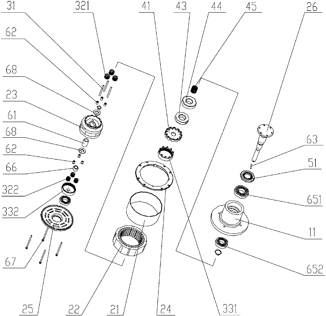
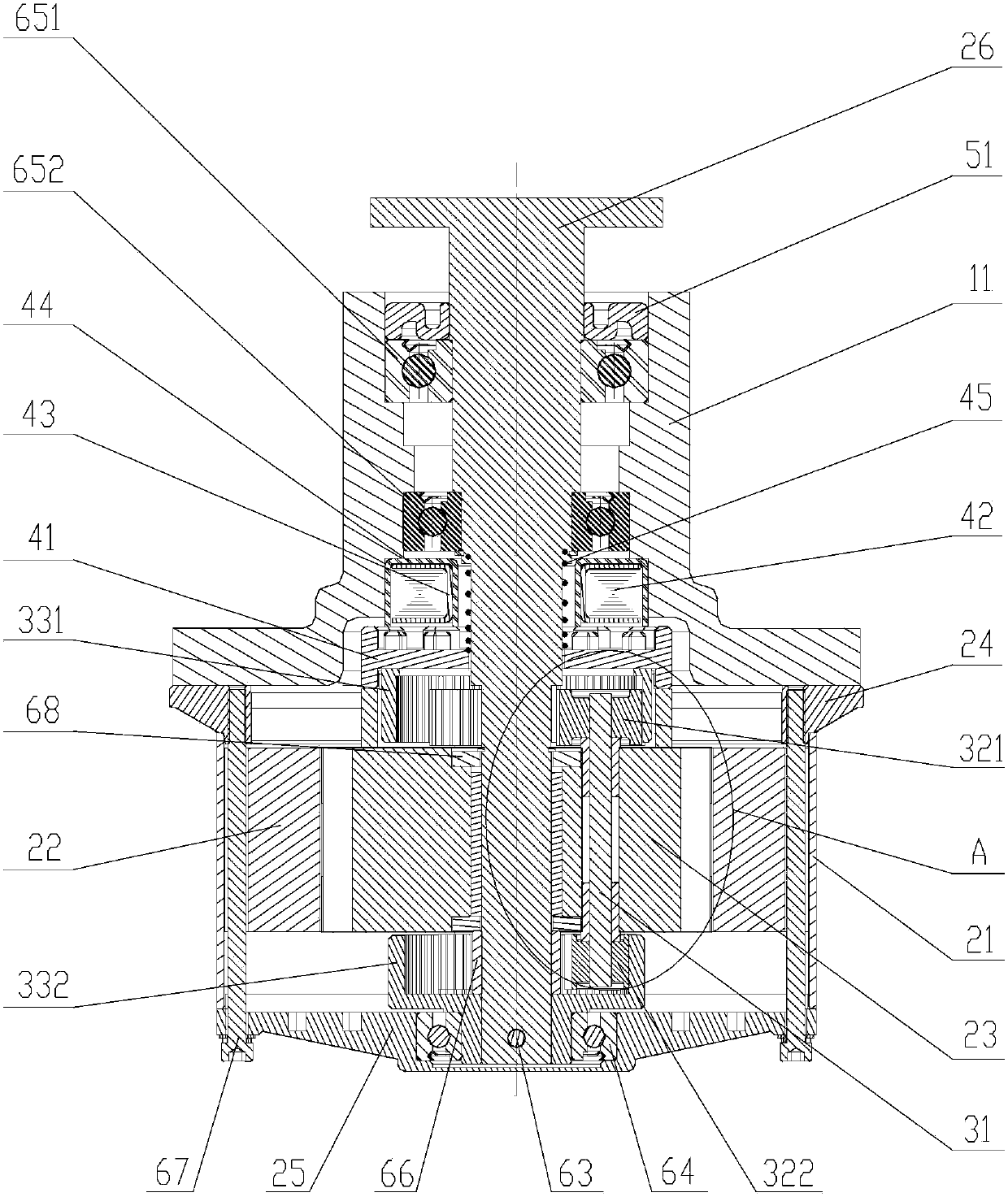
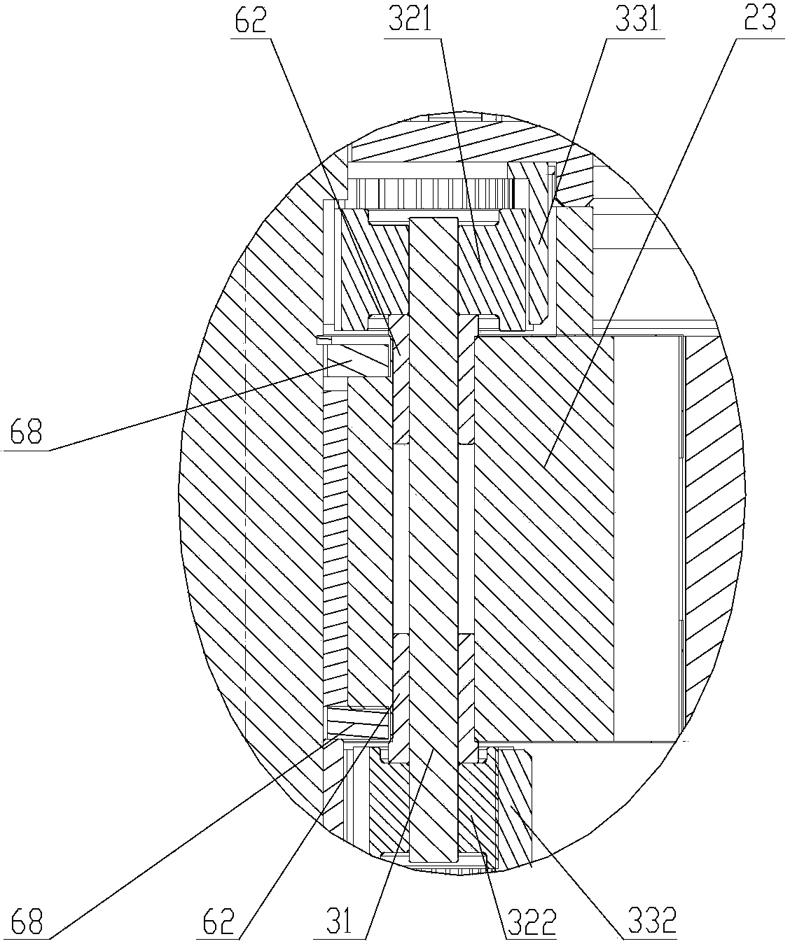
Embodiment Construction

[0025] The core of the present invention is to provide a driver for a drum washing machine, which can improve the efficiency of the motor and reduce energy consumption.

[0026] In order to enable those skilled in the art to better understand the solution of the present invention, the present invention will be further described in detail below in conjunction with the accompanying drawings and specific embodiments.

[0027] It should be pointed out that the upper, lower and other localizers involved in this article are based on Figure 1 to Figure 10 The components are located in the drawings and the positions of the components are defined only for the clarity and convenience of expressing the technical solution. It should be understood that the orientation words used herein shall not limit the scope of protection claimed in this application document.

[0028] Please refer to Figure 1 to Figure 3 , figure 1 It is an exploded schematic view of a specific embodiment of the dr...


PUM


Abstract

The invention discloses a driver of a drum washing machine, comprising a motor and an output shaft, and further comprising a gear reduction mechanism, wherein the output shaft is coaxially installed in an electronic rotor of the motor and fixedly connected with an output gear of the gear reduction mechanism, and an input gear shaft of the gear reduction mechanism is inserted-installed in a shaft hole of the motor rotor. Via the arrangement of the gear reduction mechanism, the driver of a drum washing machine provided by the invention can realize the low-speed output of the output shaft via the gear reduction mechanism during the high-speed rotation of the motor, and ensure the high-speed running of the motor in the case that the drum washing machine is in a washing working condition, thus increasing the use efficiency of the motor. Additionally, the gear reduction mechanism provided by the invention is installed on the motor, the motor rotor is used as a gear rack, and the motor and the gear reduction mechanism are effectively integrated, so that the driver is simple and compact in structure, and small in occupied space.

Description

technical field [0001] The invention relates to the technical field of drivers, in particular to a driver of a drum washing machine. Background technique [0002] The driver of the existing drum washing machine uses an AC frequency motor as the power, and the power is transmitted to the output shaft through the deceleration of the pulley, and the output shaft is connected to the inner tub of the washing machine. To realize the washing and dehydration functions of the washing machine. However, the washing and dehydrating rotation speeds of drum washing machines vary greatly. There is no deceleration device, only the pulley decelerates, and the deceleration range of the pulley is very small. The working efficiency is low at low rotating speed, which causes the existing drum washing machine to have low motor efficiency in the washing condition, and the washing time of the washing machine accounts for a large proportion in the whole working procedure, resulting in high energy c...

Claims


Application Information

Patent Timeline
Patent Type & Authority Patents(China)
IPC IPC(8): D06F37/30
Inventor 刘晓辉胡义明陈昌
Owner CHANGZHOU XINYA ELECTROMOTOR
Learn More