Forced centrifugal fine filter and engine of forced centrifugal fine filter

A fine filter and centrifugal technology, which is applied in the installation/connection of lubricant purification devices, lubricated parts, pressure lubricants, etc., can solve problems that affect the service life of components, have no purification effect, affect the crankshaft, etc., and achieve good centrifugal Filtration ability, easy to clean, easy to disassemble and replace

Active Publication Date: 2014-12-17
LONCIN MOTOR
View PDF6 Cites 0 Cited by
  • Summary
  • Abstract
  • Description
  • Claims
  • Application Information

AI Technical Summary

Problems solved by technology

[0003] In the prior art, the casing of the centrifugal fine filter is generally located on the crankshaft, which is driven by means of splines, etc. The centrifugal guide part is also arranged on the crankshaft, and the centrifugal diameter is relatively small, otherwise the radial dimension will be greatly increased ; The above-mentioned structure causes the existing centrifugal fine filter to have poor purification effect under low-speed conditions, or even has no purification effect, which affects the friction pairs such as the crankshaft and cannot be lubricated well, and affects the service life of the parts; and the above-mentioned structure needs to be used in The surface of the crankshaft opens into and out of the oil hole of the centrifugal fine filter, the processing technology is relatively complicated, and it has a bad influence on the strength of the crankshaft

Method used


Image

  • Forced centrifugal fine filter and engine of forced centrifugal fine filter

Examples


Embodiment Construction

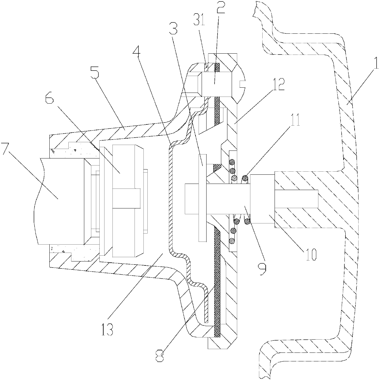
[0019] figure 1 It is a schematic diagram of the cross-sectional structure of the present invention, as shown in the figure: the forced centrifugal fine filter of the present embodiment includes a fine filter mounting seat 5 for being installed on the end of the crankshaft and fixedly matched with the fine filter in the circumferential direction and for connecting with the fine filter. The mounting base 5 together forms the sealing cover 12 of the fine filter cavity 13. As shown in the figure, the sealing cover 12 is fastened and installed on the fine filter mounting base 5 through screws 2, and a sealing gasket 8 is provided on the bonding surface to achieve a better sealing effect. Be located in fine filter cavity 13 and be fixedly connected with fine filter mounting seat 5 in circumferential direction and be provided with centrifugal separation plate 4, as shown in the figure, the rotational axis of centrifugal separation plate 4 coincides with the rotational axis of fine fi...


PUM


Abstract

The invention discloses a forced centrifugal fine filter and an engine of the forced centrifugal fine filter. A centrifugal separation plate is positioned in a fine filter cavity and is fixedly connected with a fine filter installing seat in the circumference direction, and a space allowing lubricating oil to flow is arranged between the outer edge of the centrifugal separation plate and the inner wall of the fine filter cavity. The formed centrifugal fine filter adopts the integral centrifugal separation plate structure, the problem of small centrifugal radius of an annular structure sheathed outside a crankshaft in the prior part is solved, the installation on the crankshaft is not needed, oil inlet holes and oil outlet holes do not need to be formed in the crankshaft, the integrality, the processing performance and the integral intensity of the crankshaft are ensured, and the whole separation plate has a larger centrifugal radius, so greater separation centrifugal force is generated during the rotation, and better centrifugal filtering capability is still realized under the low rotating speed conditions. When the forced centrifugal fine filter is arranged on the engine, a better centrifugal filtering effect is realized, in addition, the relatively small radial dimension is realized, the installation space is saved, the mounting, the dismounting and the cleaning are convenient, and the forced centrifugal fine filter is suitable for being used by the engine of portable vehicles of motorcycles and the like.

Description

technical field [0001] The invention relates to an accessory part of an engine and its engine, in particular to a lubricating oil filtering device and its engine. Background technique [0002] The centrifugal fine filter is an important equipment for the engine to purify the lubricating oil and ensure the normal operation of each friction pair. The centrifugal fine filter is generally driven by the rotation of the crankshaft and uses the centrifugal force of the centrifugal guide part to purify the lubricating oil, and the effect is more obvious. The centrifugal fine filter generally includes a shell and a centrifugal guide part located in the shell. After the lubricating oil enters the shell, it flows along the centrifugal guide part through centrifugal force. The solid particles with high density are located at the farthest end of the centrifugal diameter, near the center That is clean lubricating oil. [0003] In the prior art, the casing of the centrifugal fine filter ...

Claims


Application Information

Patent Timeline
Patent Type & Authority Patents(China)
IPC IPC(8): F01M11/03
Inventor 陈向东高长建彭吉文高洪军雷菊
Owner LONCIN MOTOR
Why Eureka
Try Eureka