Fan blade for industrial fan

A technology of fan blades and fans, which is applied to parts of pumping devices for elastic fluids, non-variable pumps, machines/engines, etc., can solve the problems of fan energy efficiency ratio to be improved, and achieve reduced resistance and fan efficiency Improvement, airflow noise reduction effect

Inactive Publication Date: 2012-09-12
苏州欧比特机械有限公司 +1
View PDF6 Cites 2 Cited by
  • Summary
  • Abstract
  • Description
  • Claims
  • Application Information

AI Technical Summary

Problems solved by technology

Moreover, the energy efficiency ratio of existing industrial fans also needs to be improved

Method used


Image

  • Fan blade for industrial fan
  • Fan blade for industrial fan
  • Fan blade for industrial fan

Examples


Embodiment Construction

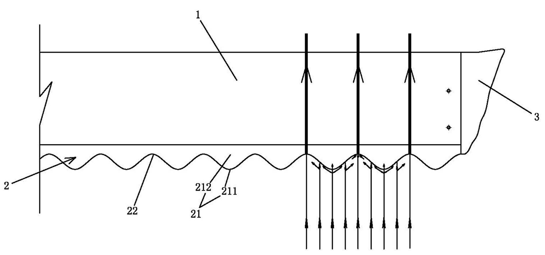
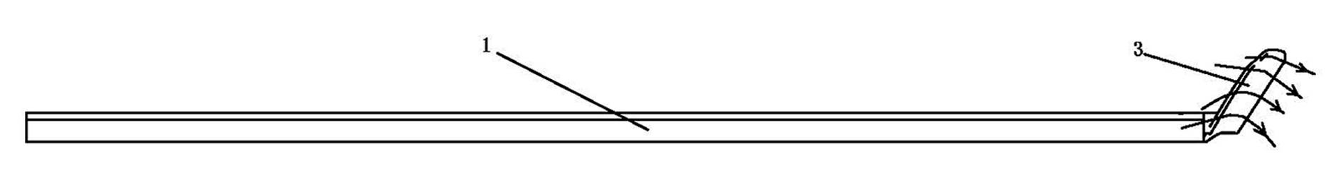
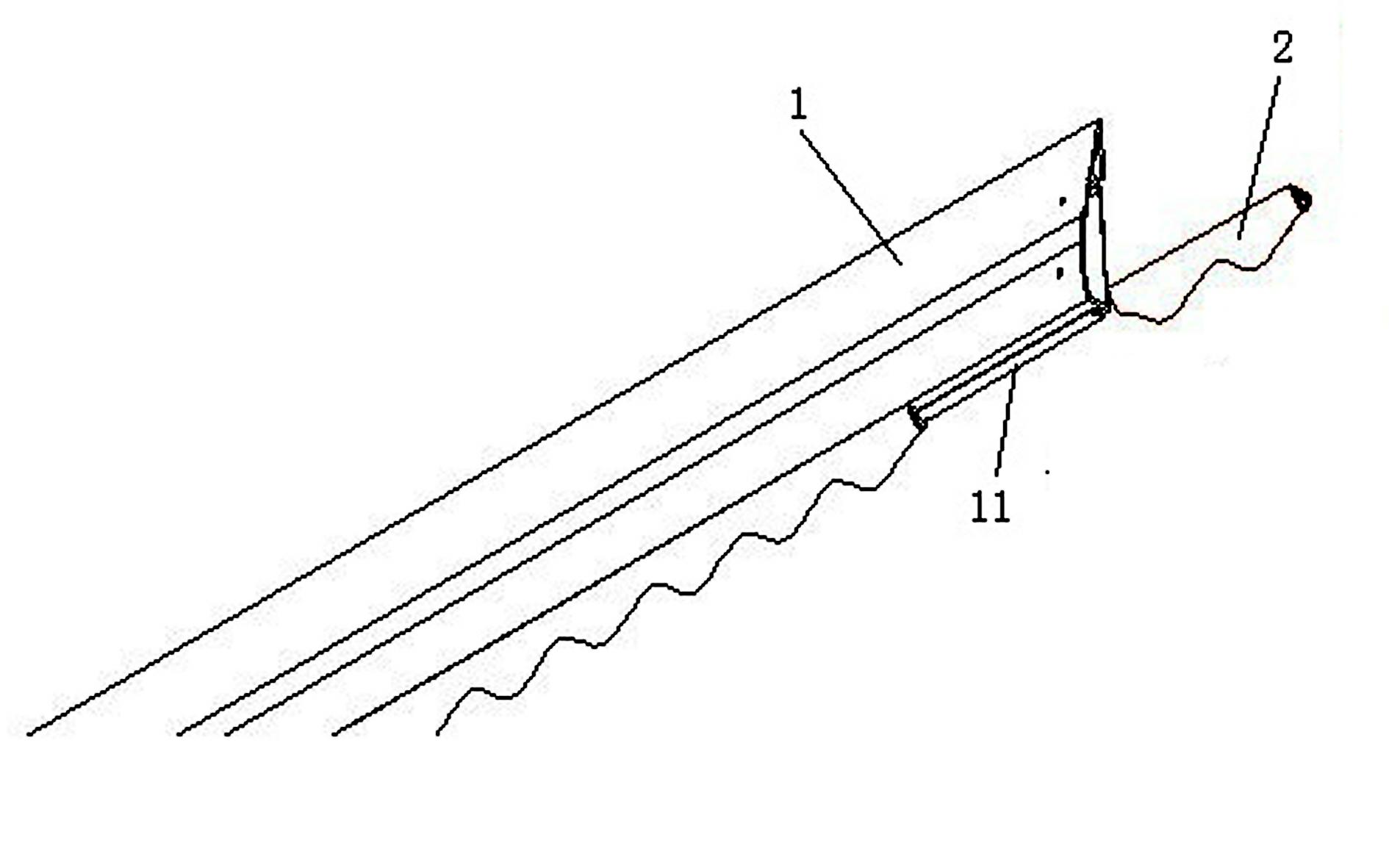
[0012] Such as figure 1 As shown, the blade of the industrial fan in this embodiment includes a blade body 1 , and a gas deflector 2 is installed on one side of the blade body 1 . Such as image 3 As shown, the specific assembly method between the gas deflector 2 and the fan blade body 1 is as follows: the gas deflector 2 is formed with a T-shaped slot (not shown in the figure), and the fan blade body 1 Only the ribs 11 matching with the slots are T-shaped in section; when assembling, snap the ribs 11 on the fan blade body 1 into the slots on the gas deflector 2 .

[0013] The gas deflector 2 is formed with several serrated protrusions 21 distributed along the length direction of the gas deflector, and a serrated valley 22 is formed between every two adjacent serrated protrusions 21 .

[0014] Moreover, in this example, one end (end) of the fan blade body 1 is also equipped with an outward expansion type winder 3 to eliminate the vortex at the end of the fan blade and achiev...


PUM


Abstract

The invention discloses a fan blade for an industrial fan. The fan blade comprises a fan blade body, wherein a gas guide plate is arranged on one side of the fan blade body; a plurality of sawtoothed bulges which are distributed along the length direction of the gas guide plate are formed on the gas guide plate; and a sawtoothed recess is formed between every two adjacent sawtoothed bulges. By the fan blade for the industrial fan, the gas flow noise during operation of the industrial fan can be reduced, and the energy efficiency ratio of the industrial fan is improved.

Description

technical field [0001] The invention relates to a fan blade of an industrial fan. Background technique [0002] Because the blades of industrial fans are generally large in size, they will emit relatively loud airflow noise when they are working. Moreover, the energy efficiency ratio of existing industrial fans also needs to be improved. Contents of the invention [0003] The object of the present invention is: to solve the above problems, provide a fan blade of an industrial fan, aiming at reducing the airflow noise when the industrial fan is working, and improving the energy efficiency ratio of the industrial fan. [0004] The technical solution of the present invention is: a blade of an industrial fan, including a blade body, a gas deflector is installed on one side of the blade body, and the gas deflector is formed with a There are several serrated protrusions distributed along the length direction of the board, and a saw-toothed valley is formed between every adjace...

Claims


Application Information

Patent Timeline
Patent Type & Authority Applications(China)
IPC IPC(8): F04D29/38
Inventor 吴成明
Owner 苏州欧比特机械有限公司
Why Eureka
Try Eureka