Ultrasonic flaw detection method for computer-assisted examination

A computer-aided, ultrasonic technology, applied in the use of sound waves/ultrasonic waves/infrasonic waves to analyze solids, etc., can solve problems such as poor quality and difficult identification, and achieve the effects of improving efficiency, ensuring the quality of flaw detection, intuitive and convenient and quick adjustment

Active Publication Date: 2014-06-18
WUXI CHEM EQUIP CO LTD
View PDF5 Cites 0 Cited by
  • Summary
  • Abstract
  • Description
  • Claims
  • Application Information

AI Technical Summary

Problems solved by technology

[0004] In view of the shortcomings of the above-mentioned existing ultrasonic flaw detection according to the table, there may be unrecognizable missed detection and poor quality, the applicant provides an ultrasonic flaw detection method with computer-aided verification, so that the predetermined value can be checked and compared. Optimize and guide flaw detection operations to avoid missed inspections

Method used


Image

  • Ultrasonic flaw detection method for computer-assisted examination
  • Ultrasonic flaw detection method for computer-assisted examination
  • Ultrasonic flaw detection method for computer-assisted examination

Examples


Embodiment Construction

[0017] The specific implementation manner of the present invention will be described below in conjunction with the accompanying drawings.

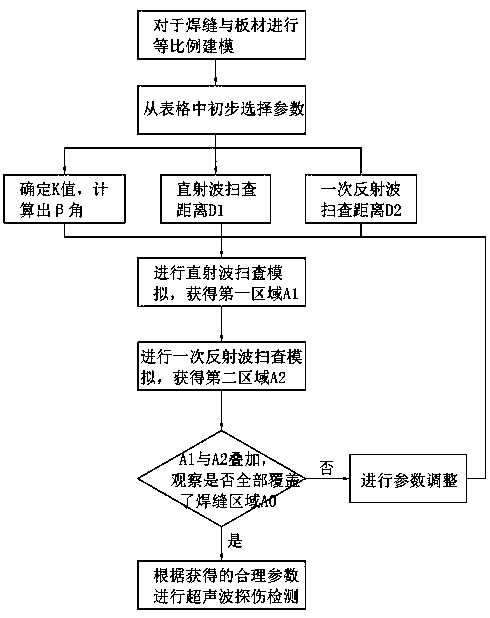
[0018] Such as figure 1 As shown, the ultrasonic flaw detection method of the computer aided checking of the present invention is divided into following steps:

[0019] The first step: computer modeling. Use drawing software on the computer, such as AutoCAD, according to the plate thickness t of the butt welded plate 1 to be detected, the type of welded joint 2 (including groove angle, blunt edge, butt gap, etc.), weld width, weld margin Advanced actual size, draw the cross-section figure of the welded joint in proportion to the actual object, and establish a two-dimensional model.

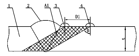
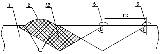
[0020] Step 2: Preliminary selection of scanning parameters from the table. Select the K value probe from "Table 18" of the "JB / T4730.3-2005" standard according to the plate thickness t; determine the direct wave according to the method of "5.1.4.1" of the ...


PUM


Abstract

The invention discloses an ultrasonic flaw detection method for computer-assisted examination. The ultrasonic flaw detection method comprises the following steps of: 1, modeling through a computer; 2, primarily selecting and scanning parameters; 3, carrying out direct wave scanning simulation; 4, carrying out primary reflected wave scanning simulation; 5, checking an area coverage condition and dynamically adjusting the parameters; and 6, carrying out actual ultrasonic flaw detection. According to the ultrasonic flaw detection method provided by the invention, the simulation states of direct waves and primary reflected wave scanning on a cross section of a welding joint can be directly emerged by using computer simulation; and meanwhile, the simulation conditions can be directly, conveniently and rapidly adjusted through dynamic real-time adjustment of a region, so that the examination and parameter adjustment efficiencies can be effectively improved. The ultrasonic flaw detection method provided by the invention can scan based on an optimal K value and flexibly adjust other parameters, so that an optimal ultrasonic image is obtained, and the flaw detection quality is ensured.

Description

technical field [0001] The invention relates to the technical field of ultrasonic flaw detection, in particular to a computer-aided ultrasonic flaw detection method. Background technique [0002] At present, the basic method used in the ultrasonic flaw detection of flat butt welded joints is to scan the entire welded joint twice by using the refracted shear wave generated by the K value probe after direct contact with the steel plate on both sides of the weld, that is, the direct wave scan Scan with a reflected wave to detect weld defects in welded joints. The current practice in the project is to select a probe with an appropriate K value according to the standard "JB / T4730.3-2005 Nondestructive Testing of Pressure Equipment Part 3: Ultrasonic Testing" according to the thickness t of the steel plate of the welded joint to be tested, and to determine the direct wave sweep Check the probe movement distance D1 and the probe movement distance D2 of a reflected wave scan, and t...

Claims


Application Information

Patent Timeline
Patent Type & Authority Patents(China)
IPC IPC(8): G01N29/04
Inventor 曹洪海过企新刘建书
Owner WUXI CHEM EQUIP CO LTD
Why Eureka
Try Eureka