Push-lean type rotary steering drilling system

A technology of rotary steerable drilling and rotary shaft, which is applied to the automatic control system of drilling, directional drilling, drilling equipment, etc., which can solve the problems of complex structure of the non-rotating outer cylinder, increased size of the drilling system, complex downhole environment, etc. Effects of smoothness and reliability, downsizing, and simplification of the internal structure

Active Publication Date: 2020-09-18
INST OF GEOLOGY & GEOPHYSICS CHINESE ACAD OF SCI
View PDF5 Cites 2 Cited by
  • Summary
  • Abstract
  • Description
  • Claims
  • Application Information

AI Technical Summary

Problems solved by technology

Corresponding circuit components are installed in the non-rotating outer cylinder. On the one hand, electrical interfaces such as conductive sockets or openings for introducing wires need to be provided at the non-rotating outer cylinder. On the other hand, corresponding circuit components need to be installed. The installation structure of other structural components, the limit structure, etc., and the need to reserve installation space for circuit components, resulting in a complex structure and an increase in the size of the non-rotating outer cylinder, resulting in an increase in the size of the entire directional drilling system. The increase in the size of the whole machine not only brings about an increase in cost, but more importantly, it affects the flexibility of the downhole feed movement of the steerable drilling system
[0007] In addition, the downhole environment is complex and harsh. During the drilling process, in order to prevent downhole impurities from entering the non-rotating outer cylinder through the joint gap between the rotating mandrel and the non-rotating outer cylinder, the non-rotating outer cylinder and the lower sub The normal operation of the electronic components in the rotating outer cylinder is affected, and the corresponding sealing structure needs to be designed, etc., the sealing cost is greatly increased, and for the technology of joint deflection driven by the hydraulic mechanism installed in the non-rotating outer cylinder, generally through The hydraulic cylinder drives the piston, and the piston drives the corresponding pushing part to expand and contract to drive the deflection of the lower joint. The expansion and contraction of the pushing part is normal in the downhole. The outer cylinder needs to be equipped with a corresponding dynamic sealing structure, which is high in cost and poor in reliability

Method used


Image

  • Push-lean type rotary steering drilling system

Examples


Embodiment 1

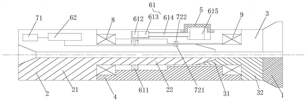
[0072] Embodiment 1: The first motion converting member 613 is a cam mechanism, the cam mechanism includes a rotating shaft and a cam sleeved on the rotating shaft, the rotating shaft is driven to rotate by the driven electromagnetic gear 612, and the connecting member One end of 614 is in contact with the cam surface of the cam. When the driven electromagnetic gear 612 drives the cam to rotate, the cam surface pushes the connecting member 614 to move linearly along the axis of the steering part 4 . Using the cam mechanism, only need to design the appropriate cam surface profile, the connecting piece can get any expected movement and stroke, and the structure is simple, compact and convenient to design.

Embodiment 2

[0073] Embodiment 2: the first motion conversion part 613 is a ball screw, the ball screw includes a screw and a nut sleeved on the screw, the screw is driven by the driven electromagnetic gear 612 to rotate, Therefore, the nut is driven to move, and the connecting member 614 is connected to the nut. The rotation of the driven electromagnetic gear 612 drives the screw to rotate, and the screw drives the nut to move linearly, so as to drive the connecting member 614 to move linearly along the axis of the steering part 4 . The ball screw is adopted, which has small friction loss and high transmission efficiency, and can realize high-speed feed and micro-feed.

[0074] At the same time, the structure of the second motion converting member 615 is not specifically limited in this embodiment, as long as the linear motion of the connecting member 614 can be converted into the movement of the pushing member 5 along the diameter of the turning portion 4 . Direct linear motion, which i...


PUM


Abstract

The invention discloses a push-lean type rotary steering drilling system comprising a drill bit, a rotary shaft, a turning part, a push-lean assembly, a transmission and a control unit. The rotary shaft comprises an upper rotary shaft and a lower rotary shaft. The turning part is arranged on the outer side of the rotary shaft in a sleeving mode. The push-lean assembly comprises a plurality of push-lean parts arranged at intervals in the circumferential direction of the turning part. The transmission device comprises a transmission mechanism driving the push-lean parts to stretch out of the turning part. The transmission mechanism comprises a driving electromagnetic gear arranged on the upper rotary shaft, and a driven electromagnetic gear arranged on the turning part. A motion conversionunit is further included and converts rotary motion of the driven electromagnetic gear into liner motion of the push-lean parts. The control unit is used for modulating a magnetic field, so that the driving and driven electromagnetic gears achieve linkage through magnetic coupling and operate with an adjustable transmission ratio. According to the push-lean type rotary steering drilling system, circuits elements, conductive sockets and the like do not need to be arranged on the turning part, the structure of the turning part is simplified, the size of the turning part is reduced effectively, flexibility of underground feed motion is improved, and cost is lowered.

Description

technical field [0001] The present application relates to the field of drilling, in particular to a push-by rotary steerable drilling system. Background technique [0002] In order to obtain natural resources stored underground, drilling exploration is required. In many cases, the wellbore and the derrick are not aligned, but need to form a certain offset or curvature, which forms a horizontal or vertical offset or other types. The process of complex boreholes is called directional drilling. The process of controlling the direction of the drill bit in the process of directional drilling is called steering. There are two types of modern directional drilling: slide-steering and rotary-steering. There are also two commonly used rotary-steering technologies, one is pointing-steering and the other is push-steering. [0003] The existing push-by rotary steerable drilling system consists of a surface monitoring system and downhole tools. The downhole tool is divided into three m...

Claims


Application Information

Patent Timeline
Patent Type & Authority Applications(China)
IPC IPC(8): E21B7/04E21B7/10E21B44/00
CPCE21B7/04E21B7/10E21B44/005
Inventor 刘庆波底青云王向阳杨永友谢棋军何新振
Owner INST OF GEOLOGY & GEOPHYSICS CHINESE ACAD OF SCI
Why Eureka
Try Eureka