Sunshine collection and guide device

A light guide device and sunlight technology, applied in light guides, lighting devices, non-electric lighting devices, etc., can solve problems such as low durability, inability to collect light stably, and large limitations, so as to avoid potential safety hazards and make The effect of low cost and large collection area

Active Publication Date: 2012-09-12
刘文
View PDF6 Cites 2 Cited by
  • Summary
  • Abstract
  • Description
  • Claims
  • Application Information

AI Technical Summary

Problems solved by technology

[0004] The existing sunlight introduction technology, because of the straight-line propagation characteristics of the light, all adopts the moving conduction through the optical fiber, or the fixed conduction through the reflection; the moving conduction is to use the total reflection of the light in the optical fiber and finally transmit it to the required lighting and lighting. Where it is used, commonly used optical fibers include plastic optical fibers and quartz optical fibers. Plastic optical fibers are light and soft, have stronger resistance to vibration and bending damage, and take up less space and are relatively low in cost, but their long-distance The light loss of transmission is relatively large, so it can only be used for short-distance transmission.
Silica optical fiber has excellent heat resistance and good light transmission performance, but its cost is high, its durability is low, and its use cost is high, which leads to the complexity and high cost of the existing sunlight transmission and utilization devices
Although the cost of fixed conduction is very low, the transmission line of light must be fixed. It is also due to the straight-line propagation of light that the light cannot be collected stably and cannot change accordingly with the movement of the sun. Therefore, its limitations are large and the scope of application Small, poorly effective, unable to move conduction

Method used


Image

  • Sunshine collection and guide device
  • Sunshine collection and guide device
  • Sunshine collection and guide device

Examples


Embodiment Construction

[0024] The present invention will be further described below in conjunction with the accompanying drawings and preferred embodiments.

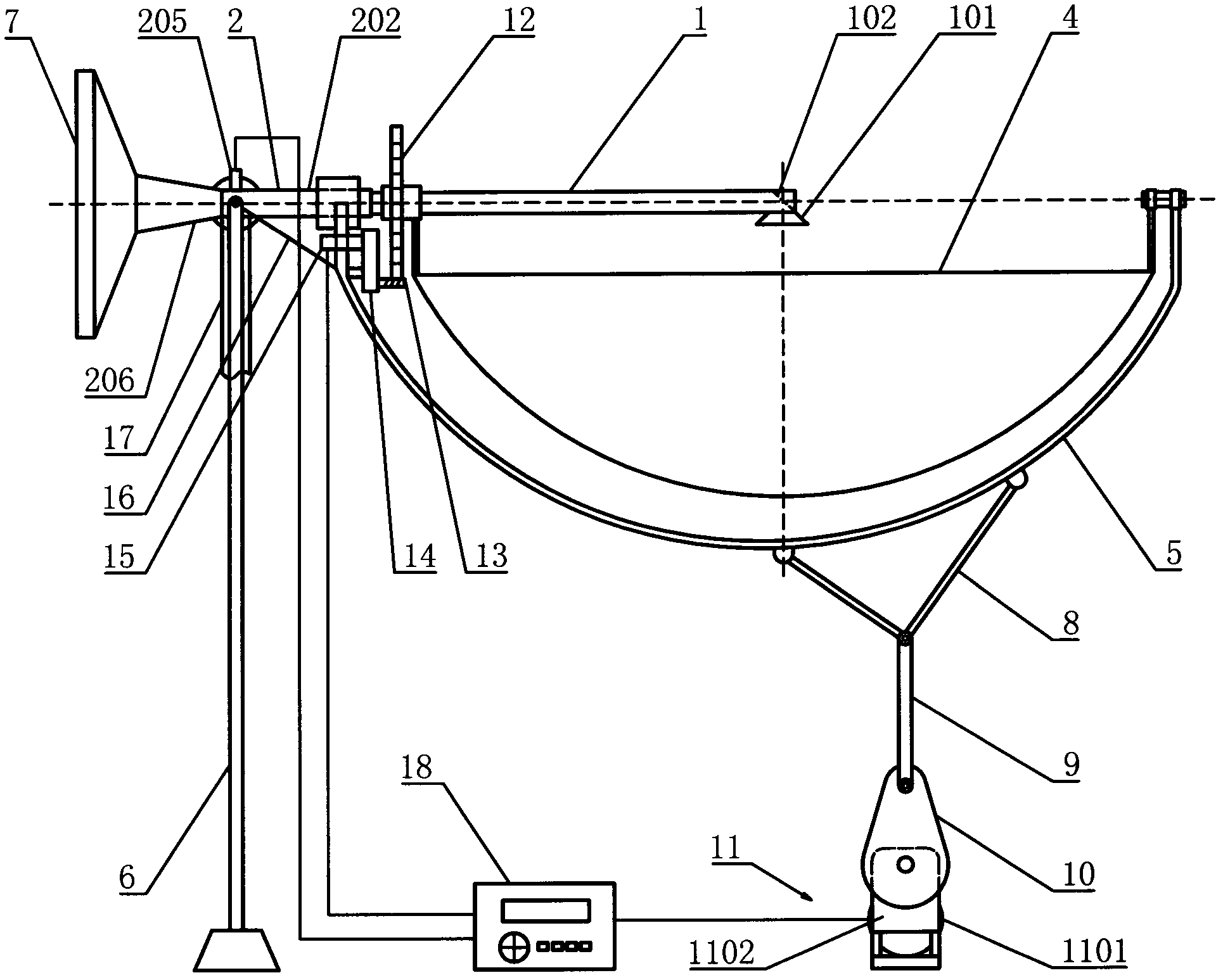
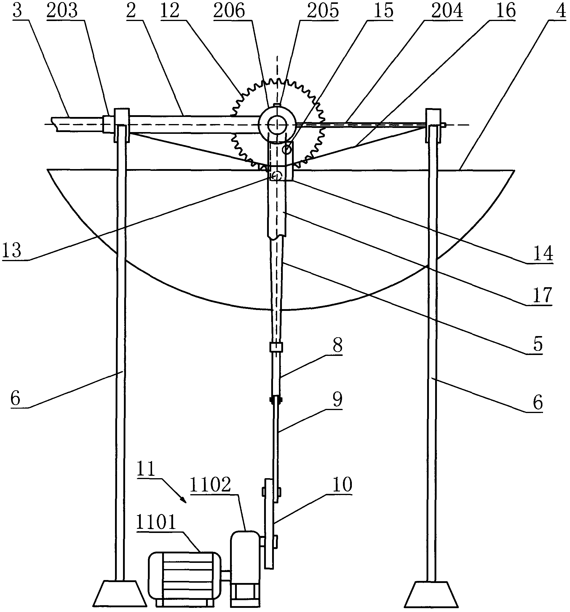
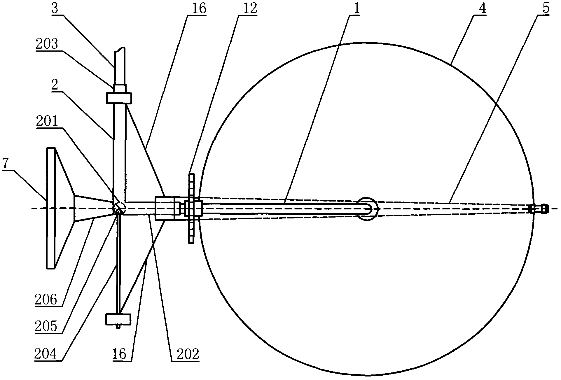
[0025] The sunlight collecting and guiding device of the present invention, such as figure 1 As shown, it includes a collection device and a guide device, and an electric control box 18 connected to the collection device and the guide device respectively, wherein the guide device includes a central light guide 1, a fixed sleeve 2 and a side light guide 3 ,Such as image 3 As shown; the fixed sleeve 2 is L-shaped, and a light turning device 201 is arranged inside the corner, which is used to change the direction of the light transmitted from the central light guide tube 1; one end of the fixed sleeve 2 is the light incident end 202 and The rotating sleeve is provided with a central light guide tube 1, which ensures that the central light guide tube 1 can rotate along its central axis; The light guide 3 can complete the axial rotation along it...


PUM


Abstract

The invention relates to a sunshine utilization device, in particular to a sunshine collection and guide device which has a simple structure, is low in cost and can transmit sunshine in a mobile manner through reflection. The sunshine collection and guide device comprises a collection device, a guide device and an electric control box (18) which is respectively connected with the collection device and the guide device, wherein the guide device comprises a central light guide pipe (1), a fixed sleeve (2) and a lateral light guide pipe (3); the fixed sleeve (2) is L-shaped; a light ray steering device (201) is arranged in the corner of the fixed sleeve (2); one end of the light ray steering device (201) is a light inlet end (202) and sleeved with the central light guide pipe (1) in a rotatable manner; the other end of the light ray steering device (201) is a light outlet end (203) and sleeved with the lateral light guide pipe (3) in a rotatable manner; a supporting rod (204) opposite to the light outlet end (203) extends out of the fixed sleeve (2); a light ray inlet (101) is formed at the free end of the central light guide pipe (1); and a light ray reflection mirror (102) is arranged in the light ray inlet (101).

Description

technical field [0001] The invention relates to a device for utilizing sunlight, in particular to a sunlight collecting and guiding device. Background technique [0002] Sunlight, air, and water are the three elements of life on earth. Light is the most common, but it is also the most easily overlooked. Sunlight is the most important natural light source. In addition to sunlight, there are other light sources, such as the lights used in our daily life. It is an artificial light source, which is much weaker than sunlight, and the proportion of visible light contained is also the same as that of sunlight. Sunshine is different. Generally, the light emitted by incandescent lamps is often reddish and yellowish, while the light emitted by fluorescent lamps is blueish. With the acceleration of the pace of modern life, people have fewer and fewer opportunities to be in contact with sunlight; the increasing tension of urban land also makes more buildings unable to enjoy the sunlig...

Claims


Application Information

Patent Timeline
Patent Type & Authority Applications(China)
IPC IPC(8): G02B19/00G02B6/00G02B7/198G05D3/00F21S11/00H02N6/00H02S40/20H02S40/22
CPCY02E10/52
Inventor 刘文
Owner 刘文
Why Eureka
Try Eureka