Automobile exhaust waste heat recycling device

A technology for waste heat recovery and automobile exhaust, which is applied to exhaust devices, mufflers, electrical components, etc., can solve the problems of not improving the environmental protection of automobile exhaust pollution, affecting the cost performance of the whole vehicle, and affecting the promotion of widespread development, etc., to improve the utilization of space volume. efficiency, reduce processing costs, and increase the effect of heat exchange recovery area

Inactive Publication Date: 2017-11-17
WUHAN UNIV OF TECH
View PDF1 Cites 2 Cited by
  • Summary
  • Abstract
  • Description
  • Claims
  • Application Information

AI Technical Summary

Problems solved by technology

[0002] Automobile exhaust temperature difference power generation is a method of energy recovery and reuse of automobile exhaust, but the existing automobile exhaust temperature difference power generation system is large in size and low in power generation efficiency, which affects the cost performance of the whole vehicle
In addition, the existing automobile exhaust temperature differential power generation system has a single function, which can only achieve the energy-saving effect of partial energy recovery, and cannot improve the current environmental protection problems of serious automobile exhaust pollution, and the excessive volume and low cost performance have also affected the application of this technology in automobiles. Wide promotion in the field

Method used


Image

  • Automobile exhaust waste heat recycling device
  • Automobile exhaust waste heat recycling device
  • Automobile exhaust waste heat recycling device

Examples


Embodiment Construction

[0025] The present invention will be described in detail below in conjunction with the accompanying drawings and embodiments.

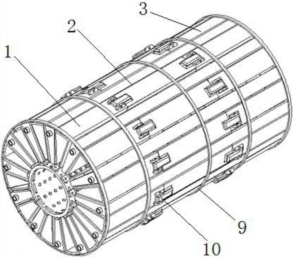
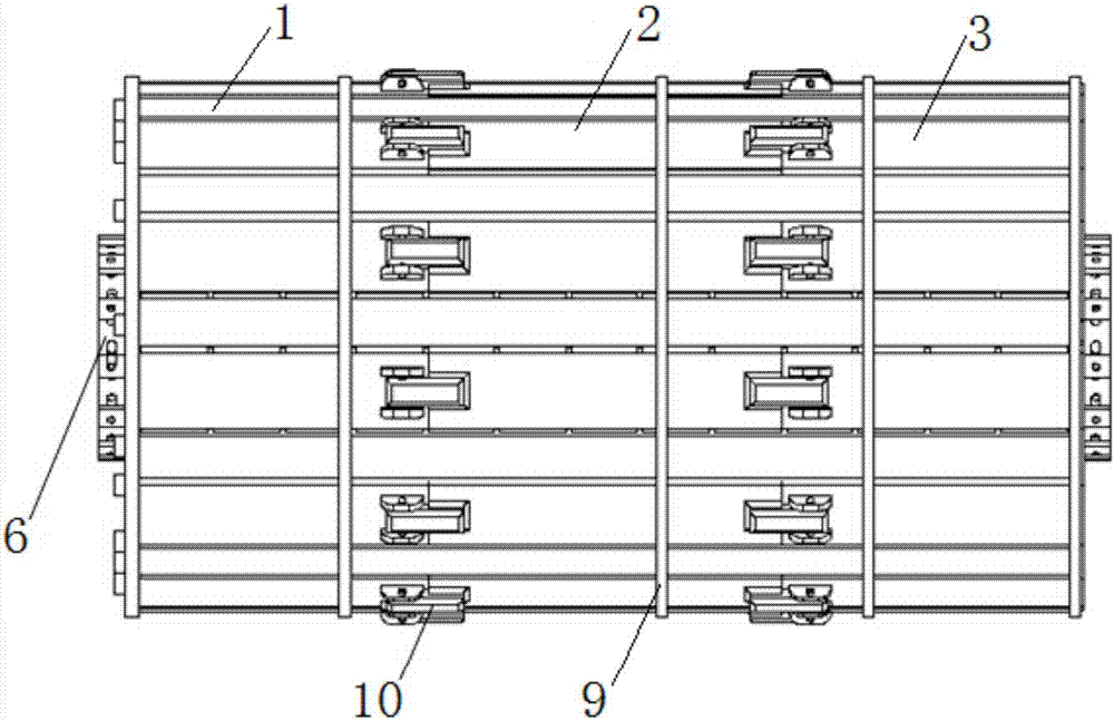
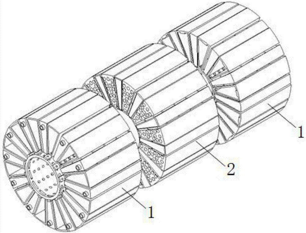
[0026] refer to Figure 1 to Figure 7 As shown, the automobile exhaust waste heat recovery and utilization device in an embodiment provided by the present invention includes two waste heat power generation components 1 and an SCR power generation component 2, and the two waste heat power generation components 1 are respectively arranged at both ends of the SCR power generation component 2;

[0027] Wherein, the cogeneration unit 1 comprises an exhaust gas pipeline 6, a plurality of air tanks 4 and a plurality of water tanks 5, and the plurality of air tanks 4 and the plurality of water tanks 5 are uniformly distributed along the central axis of the exhaust gas pipeline 6, and the gas tanks 4 and water tanks 5 cross distribution, the temperature difference power generation module 3 is connected between the gas tank 4 and the water tank 5, and a plurali...


PUM


Abstract

The invention discloses an automobile exhaust waste heat recycling device. The automobile exhaust waste heat recycling device comprises two waste heat power generation parts and an SCR power generation part, and the waste heat power generation parts are arranged at the two ends of the SCR power generation part respectively; each waste heat power generation part comprises an exhaust pipeline, multiple gas tanks and multiple water tanks, wherein the gas tanks and the water tanks are circumferentially and uniformly distributed along the central axis of the exhaust pipeline and distributed in a crossed mode, a temperature differential power generation module is arranged between each gas tank and the corresponding water tank, and the gas tanks are communicated with the exhaust pipeline through vent holes; and the SCR power generation part comprises a middle shaft, multiple SCR reaction devices and multiple water tanks, the SCR reaction devices and the water tanks are circumferentially and uniformly distributed along the central axis of the middle shaft and distributed in a crossed mode, a temperature differential power generation module is arranged between each SCR reaction device and the corresponding water tank, and the two ends of each SCR reaction device are communicated with the gas tanks corresponding to the two ends of the SCR reaction device respectively. The device is of a multi-stage heat recycling structure, the overall size is decreased, and the exhaust heat recycling rate and the power generation rate are increased.

Description

technical field [0001] The invention relates to the technical field of automobiles, in particular to a device for recovering and utilizing waste heat from automobile exhaust. Background technique [0002] Automobile exhaust temperature difference power generation is a method of energy recovery and reuse of automobile exhaust. However, the existing automobile exhaust temperature difference power generation system has a large volume and low power generation efficiency, which affects the cost performance of the whole vehicle. In addition, the existing automobile exhaust air temperature difference power generation system has a single function, which can only achieve the energy saving effect of partial energy recovery, and cannot improve the current environmental protection problems of serious automobile exhaust pollution, and the excessive volume and low cost performance have also affected the application of this technology in automobiles. Widespread promotion in the field. Co...

Claims


Application Information

Patent Timeline
Patent Type & Authority Applications(China)
IPC IPC(8): H02N11/00F01N5/02
CPCH02N11/002F01N5/025Y02T10/12
Inventor 邓亚东姚云龙董文彬苏楚奇
Owner WUHAN UNIV OF TECH
Why Eureka
Try Eureka