Steel reed dent measurement device

A measuring device and reed technology, applied in the direction of instruments, counting mechanisms/items, etc., to achieve the effects of strong anti-interference, accurate counting results, and improved accuracy and efficiency

Inactive Publication Date: 2012-09-12
SHAOXING UNIVERSITY
View PDF2 Cites 2 Cited by
  • Summary
  • Abstract
  • Description
  • Claims
  • Application Information

AI Technical Summary

Problems solved by technology

The beam emitting element emits the laser beam

Method used


Image

  • Steel reed dent measurement device
  • Steel reed dent measurement device
  • Steel reed dent measurement device

Examples


Embodiment Construction

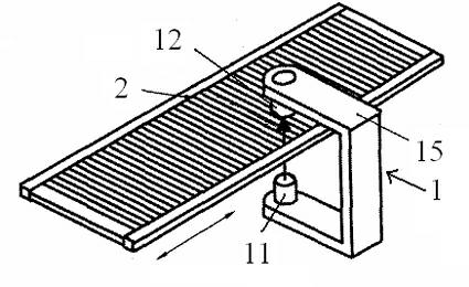
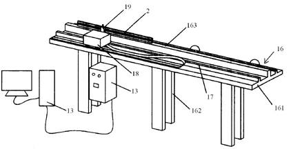
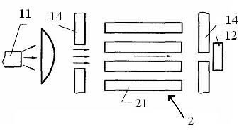
[0015] figure 1 Shown is a partial schematic view of the reed tooth measuring device provided by the present invention. figure 2 Shown is a schematic diagram of the reed tooth measuring device provided by the present invention. image 3 Shown is a schematic diagram of the principle of the reed tooth measuring device provided by the present invention. Please also refer to Figure 1 to Figure 3 .

[0016] The invention provides a reed tooth measuring device 1 for measuring the number of reed teeth of a steel reed 2 to be tested. The reed tooth measuring device 1 includes a beam emitting element 11 , a photosensitive receiving element 12 and a processing unit 13 . The beam emitting element 11 emits a laser beam. The beam emitting element 11 and the photosensitive receiving element 12 are respectively arranged on both sides of the reed 2 to be tested. The laser beam is emitted by the beam emitting element 11 and received by the photosensitive receiving element 12 after pass...


PUM


Abstract

The invention provides a steel reed dent measurement device which is used for measuring the number of dents of steel reed to be measured. The steel reed dent measurement device comprises a light beam emission element, a photosensitive receiving element and a processing unit, wherein the light beam emission element emits a laser beam; the light beam emission element and the photosensitive receiving element are respectively arranged on two sides of the steel reed to be measured; the laser beam is emitted by the light beam emission element and received by the photoelectric receiving element after passing through the steel reed to be measured; the steel reed to be measured does perpendicular motion relative to the laser beam; and the processing unit is electrically connected with the photosensitive receiving element and used for generating a measurement result. The steel reed dent measurement device can automatically measure the number of the dents of the steel reed, so that the technical problem of manual measurement in the prior art is solved, and the precision and the efficiency are improved.

Description

technical field [0001] The invention relates to a testing device for matching equipment of a loom, in particular to a measuring device for steel reed teeth. Background technique [0002] The reed is the key supporting equipment of the loom. The loom relies on the reed to swing back and forth to push the weft yarns introduced into the shed one by one to the weaving fell, and interweave with the warp yarns passing between the reed teeth to form a fabric that meets the design requirements. On the loom, the main functions of the reed are: 1. Evenly arranged, so that the warp yarns are arranged in a certain order, which directly determines the warp yarn density of the fabric; 1. The special-shaped reed of the air-jet loom has the function of assisting airflow weft insertion; 3. The weft yarn introduced into the shed is evenly driven into the weaving mouth to form a fabric. [0003] Therefore, the correctness of the dimensions of the reed directly affects the quality of the weavi...

Claims


Application Information

Patent Timeline
Patent Type & Authority Applications(China)
IPC IPC(8): G06M1/272
Inventor 张新华张若煜
Owner SHAOXING UNIVERSITY
Why Eureka
Try Eureka