Method for detecting remote sensing image change based on adaptive difference images

A remote sensing image and change detection technology, which is applied in the field of digital image processing in environment and urban planning, can solve the problems of high preprocessing requirements of remote sensing image data, reduce the visual effect of the changed area, affect the change detection results, etc., and improve the accuracy of detection performance, reduce the impact of missed detection, and ensure the effect of accuracy

Inactive Publication Date: 2012-09-12
XIDIAN UNIV
View PDF6 Cites 14 Cited by
  • Summary
  • Abstract
  • Description
  • Claims
  • Application Information

AI Technical Summary

Problems solved by technology

This method is relatively simple, direct, and easy to implement. The disadvantage is that the obtained difference image requires high preprocessing of remote sensing image data, and the noise in the difference image has a great impact on the detection results.
[0004] In order to improve the detection effect of direct difference images and improve the accuracy of change detection, scholars such as Lingcao Huang proposed a weighted fusion Sobel edge texture map and difference difference map in the article "An Object-based Change Detection Approach by Integrating Intensity and Texture Differences" The probability difference map is obtained, and the threshold is used to segment the fused probability difference map to obtain a change detection image. While maintaining the change area, a large number of noise points are introduced, which affects the result of change detection.
Wei He proposed in the article "Application of Euclidean norm in Multi-temporal Remote Sensing Image Change Detection" to use the Euclidean distance norm of the difference between two remote sensing images to represent the difference map, and then use the maximum entropy threshold method to extract the change part. This method suppresses noise information, but does not maintain details such as edges well, reducing the visual effect of changing areas

Method used


Image

  • Method for detecting remote sensing image change based on adaptive difference images
  • Method for detecting remote sensing image change based on adaptive difference images
  • Method for detecting remote sensing image change based on adaptive difference images

Examples


Embodiment Construction

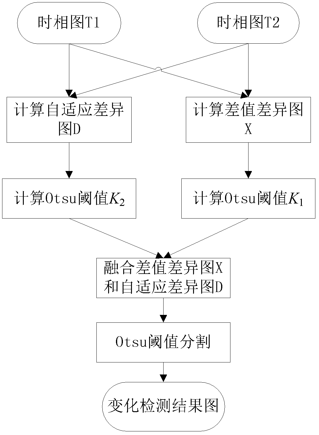
[0022] refer to figure 1 , the implementation of the present invention is as follows:

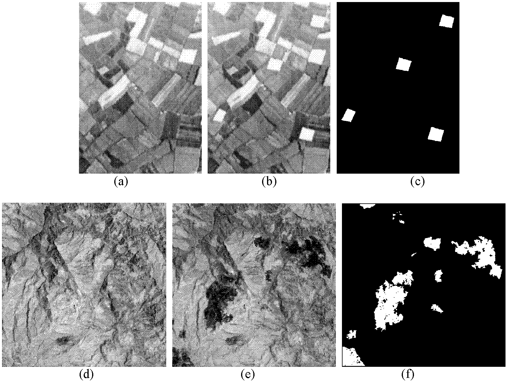
[0023] Step 1, input two registered multi-temporal remote sensing images T1 and T2, and convert the pixel gray value at the corresponding position (x, y) of image T1 and image T2 and Calculate the difference and get the difference difference map 1≤x≤M, 1≤y≤N, where M is the length of the remote sensing image T1, and N is the width of the remote sensing image T1.

[0024] Step 2, take a sliding window E of size 3×3 for the first image T1 centered on pixel i i , for the second image T2, take the pixel point i as the center and take the search window G of 7×7 pixels i , i is the current pixel point, in the search window G i Take a sliding window with a size of 3×3 pixel by pixel to get a set of sliding windows {F j}, F j is a sliding window with j as the center point in the sliding window set, and j is the search window G i Any pixel point within, set the sliding window set {F j Th...


PUM


Abstract

The invention discloses a method for detecting remote sensing image change based on adaptive Treelet construction difference images, belongs to the field of image processing technology and mainly assists in solving a problem of change detection precision deficiency in the prior art. The method is realized by carrying out block processing of two inputted different-phase remote sensing images, namely calculating difference values between an image block in a search window of a second image and a center image block of a first image to obtain sample matrixes; clustering the sample matrixes by using Treelet algorithm to obtain adaptive difference images; calculating Otsu thresholds of differential-value difference images and adaptive difference images; integrating the differential-value difference images and the adaptive difference images by using the thresholds to obtain final difference images, and carrying out Otsu threshold segmentation on the final difference images to obtain change detection results. According to the method in the invention, change detection precision can be improved effectively; image edge information can be maintained; and the method can be used for detecting disaster situation and in land utilization.

Description

technical field [0001] The invention belongs to the technical field of digital image processing, in particular to a remote sensing image change detection method based on an adaptive Treelet structure difference map, which is suitable for digital image processing in environment and urban planning. Background technique [0002] The change detection of remote sensing images refers to the analysis of remote sensing images of the same geographical location in different periods to obtain the change information, which is the main development direction of the current remote sensing data processing technology. [0003] The change detection method of two remote sensing images after registration is usually to obtain the difference image through direct operation, and then analyze and process the difference image to obtain the detection result map of the classification of change and non-change. This method is relatively simple, direct, and easy to implement. The disadvantage is that the ...

Claims


Application Information

Patent Timeline
Patent Type & Authority Applications(China)
IPC IPC(8): G06T7/00
Inventor 王桂婷焦李成曹娟钟桦田小林张小华公茂果王爽
Owner XIDIAN UNIV
Why Eureka
Try Eureka