

Method for adaptively determining optimal polarization orientation in polarization vision system
A technology of vibration transmission direction and vision system, which is applied in image data processing, instruments, calculations, etc., and can solve the problem of being unable to quickly and objectively determine the transmission direction of polarizers.
- Summary
- Abstract
- Description
- Claims
- Application Information
AI Technical Summary
Problems solved by technology
Method used
Image

Examples
Embodiment Construction
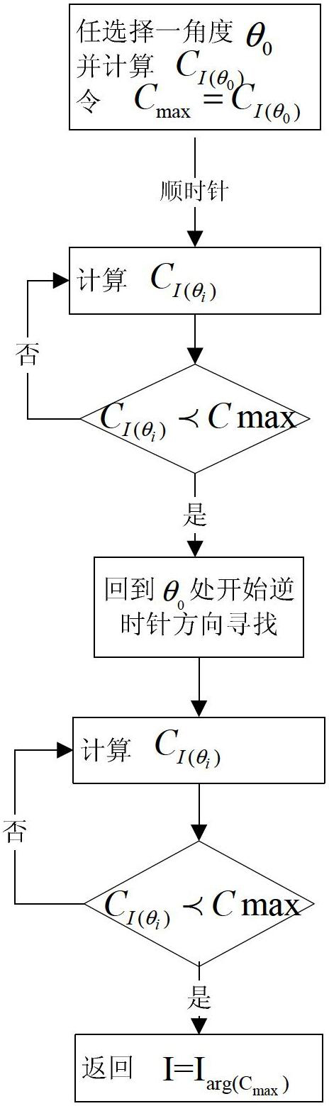
[0048] like Figure 4 As shown, the method for adaptively determining the optimal vibration transmission direction of the polarizer in the polarization vision system includes the following steps:
[0049] 1) Use the polarization images of any three polarizers with known transmission directions to synthesize polarization images in any transmission direction;
[0050] When the angle between the transmission direction of the polarization image and the reference direction (selected 0° direction) is θ, the polarization image in any transmission direction can be expressed as:
[0051] I ( θ ) = 1 2 I + 1 2 Q cos 2 θ + 1 2 U sin 2 θ - - - ( 1 ...
PUM
 Abstract
Description
Claims
Application Information