Passive permanent magnet coupling transmission, braking or load device

A technology of permanent magnetic coupling and load device, applied in the direction of asynchronous induction clutch/brake, electromechanical device, electrical components, etc.

Active Publication Date: 2012-09-12
YANGZHOU UNION TRANSMISSION TECH
View PDF14 Cites 63 Cited by
  • Summary
  • Abstract
  • Description
  • Claims
  • Application Information

AI Technical Summary

Problems solved by technology

[0003] During the implementation and promotion of the above-mentioned permanent magnetic coupling patents, we found that there is an urgent problem to be solved, that is, all current permanent magnetic couplings (PMC), permanent magnetic coupling speed controllers (PMD), permanent magnetic coupling speed control couplings The permanent magnetic coupling automatic transmission, permanent magnetic coupling brake device, permanent magnetic coupling load/loading device and permanent magnetic coupling clutch all realize the axial adjustment between the active rotor disc and the passive rotor disc through the permanent magnetic coupling axial displacement adjustment mechanism. The change of the axial relative position of the permanent magnetic coupling assembly, so as to realize the change of the air gap distance and the air gap coupling area in the permanent magnetic coupl

Method used


Image

  • Passive permanent magnet coupling transmission, braking or load device
  • Passive permanent magnet coupling transmission, braking or load device
  • Passive permanent magnet coupling transmission, braking or load device

Examples


Embodiment 1

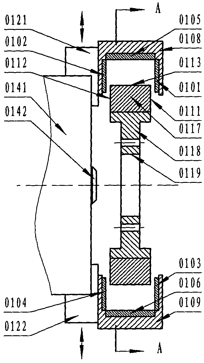
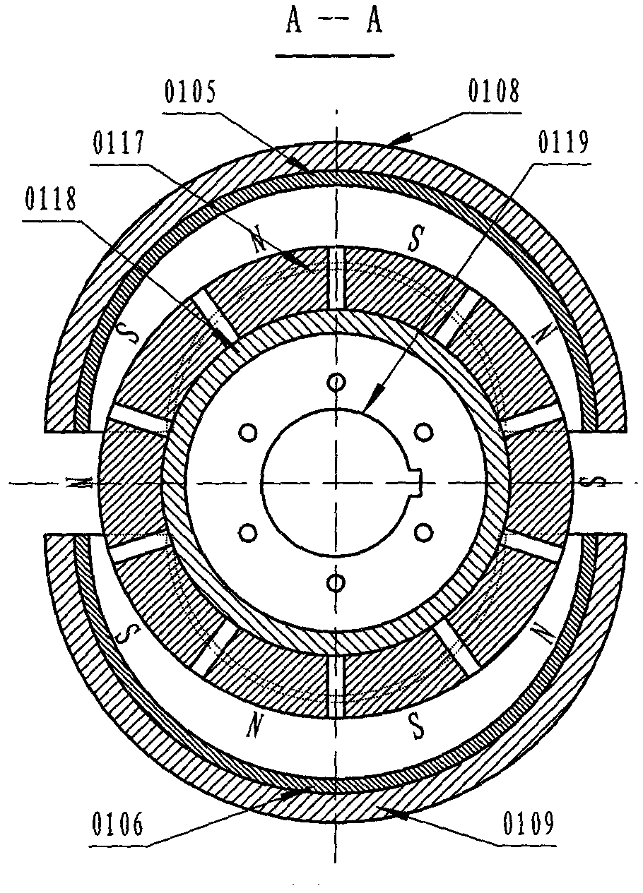
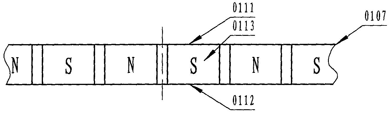
[0088] Example 1. As Figure 1 to Figure 10 As shown, it is a permanent magnet coupling governor (PMD) with a dual petal-shaped axial-radial magnetic field compound structure, which is mainly assembled from the following components: four pairs of axial magnetic field petal-shaped metal conductor armature discs (0101, 0102, 0103, 0104), two pairs of radial magnetic field petal-shaped metal conductor armature disks (0105, 0106), one pair of disc-shaped permanent magnet disks with 3 coupling surfaces (0111, 0112, 0113) ( 0117), a pair of active rotor disc coupling mechanisms consisting of a disc-shaped permanent magnet group mounting plate (0118) and its shaft hole (0119), a pair of two petal-shaped metal conductor armature mounting plates (0108, 0109 ), two chuck claws (0121, 0122), the chuck body (0141) and the central short shaft (142) constitute the passive rotor disc coupling mechanism, and two petal-shaped metal conductor armature mounting discs (0108, 0109) Fasten and ins...

Embodiment 2

[0090] Example 2. If Figure 11 to Figure 14 As shown, it is a permanent magnet coupling governor (PMD) with a dual petal-shaped axial-radial magnetic field compound structure, which is mainly assembled from the following components: four pairs of axial magnetic field petal-shaped metal conductor armature discs (0201, 0202, 0203, 0204), two flap-shaped squirrel-cage armature disks (0205, 0206), one disk-shaped permanent magnet disk (0217) with 3 coupling surfaces (0211, 0212, 0213), One pair of active rotor disk coupling mechanism consisting of disk-shaped permanent magnet group mounting plate (0218) and its shaft hole (0219), one pair of two petal-shaped composite armature mounting plates (0208, 0209), two Chuck jaws (0221, 0222), chuck body (0241) and central short shaft (242) constitute the passive rotor disk coupling mechanism, and two petal-shaped composite armature mounting disks (0208, 0209) are respectively connected with two chucks. The disc claws (0221, 0222) are fa...

Embodiment 3

[0091] Example 3. As Figure 15 to Figure 18As shown, it is a permanent magnetic coupling governor with a double petal-shaped axial-radial magnetic field compound structure, which is mainly assembled from the following components: four petal-shaped pot grate armature discs (0301, 0302, 0303 , 0304), two flap-shaped squirrel-cage armature discs (0305, 0306), a disc-shaped permanent magnet disc (0317) with three coupling surfaces (0311, 0312, 0313), a disc-shaped The active rotor disk coupling mechanism composed of the permanent magnet group mounting plate (0318) and its shaft hole (0319), a pair of two petal-shaped composite armature mounting plates (0308, 0309), two chuck claws (0321, 0322), the chuck body (0341) and the central short shaft (0342) constitute the passive rotor disc coupling mechanism, the radial displacement component is a "seesaw" type, mainly composed of L-shaped seesaws (0351, 0352), chuck body ( 0341), chuck jaws (0321, 0322), mobile connection plate (0367...


PUM


Abstract

The invention discloses a passive permanent magnet coupling transmission, braking or load device which is of a petal-shaped rotary plate type, petal-shaped rotary cylinder type or petal-shaped composite type structure, wherein the passive permanent magnet coupling transmission, braking or load device consists of at least one petal-shaped permanent magnet coupling component, at least one driving rotor plate coupling mechanism, at least one driven rotor plate coupling mechanism and at least one permanent magnetic coupling radial telescopic displacement regulating mechanism, wherein the at least one permanent magnetic coupling radial telescopic displacement regulating mechanism is used for implementing the variation regulation of an air clearance coupling area and a coupling pitch; the petal-shaped permanent magnet coupling component comprises a conductor armature type structure, a mouse cage armature type structure, a boiler grate armature type structure, a winding armature type structure, a dual-permanent-magnet type structure and a composite type structure, and a refrigerant cooling device and a locking/clutching device are configured as required. The passive permanent magnet coupling transmission, braking or load device provided by the invention is suitable for the technical field of transmission of transmission shafts, the technical field of speed regulation, the technical field of braking, the technical field of energy conservation and emission reduction, the technical field of load/uploading as well as the technical field of cutting off/combination motive power, and is used for designing the technical scheme for manufacturing related products of permanent magnet coupling driving, speed regulating, moment changing, braking or loading devices and the like.

Description

technical field [0001] The technical fields involved in the present invention include: the technical field of transmission shaft coupling drive and speed regulation, the technical field of energy saving and emission reduction, the technical field of cutting / combining power, the technical field of braking, the technical field of loading / loading of power equipment dynamometer, especially a A passive permanent magnetic coupling drive, brake or load device. Background technique [0002] Around us, there are many systems or devices related to the coupling transmission between the power equipment output shaft and the load input shaft and its load speed regulation technology, the rotation braking technology, the power equipment dynamometer and its simulated load technology. Permanent magnetic coupling transmission technology, braking technology and dynamometer load technology are in the ascendant, and the market demand is expanding day by day. Permanent magnet coupling transmissio...

Claims


Application Information

Patent Timeline
IPC IPC(8): H02K49/04
CPCH02K2213/09
Inventor 林贵生余亚莉
Owner YANGZHOU UNION TRANSMISSION TECH
Why Eureka
Try Eureka