Operation planning method, operation planning device, heat pump hot water supply system operation method, and heat pump hot water supply and heating system operation method

A technology of operation plan and operation method, which is applied in the field of equipment systems, can solve the problems of reducing the reverse flow of the flow system and has no effect, and achieve the effect of reducing damage

Inactive Publication Date: 2012-09-12
PANASONIC CORP
View PDF5 Cites 6 Cited by
  • Summary
  • Abstract
  • Description
  • Claims
  • Application Information

AI Technical Summary

Problems solved by technology

However, this excess electricity is not used to operate the heat pump u

Method used


Image

  • Operation planning method, operation planning device, heat pump hot water supply system operation method, and heat pump hot water supply and heating system operation method
  • Operation planning method, operation planning device, heat pump hot water supply system operation method, and heat pump hot water supply and heating system operation method
  • Operation planning method, operation planning device, heat pump hot water supply system operation method, and heat pump hot water supply and heating system operation method

Examples


Embodiment 1

[0055] (Example 1: Heat pump hot water supply device)

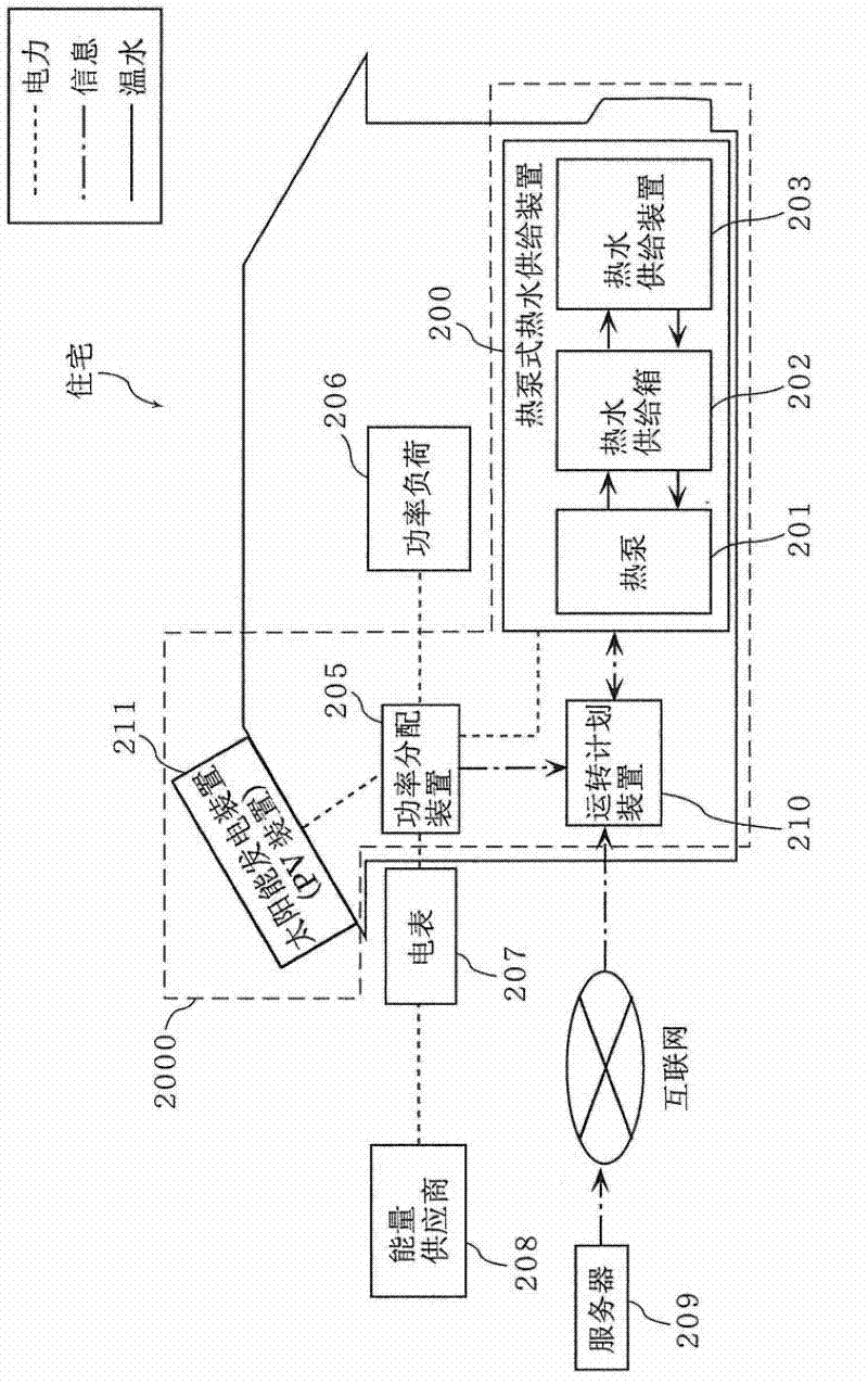
[0056] figure 2 A heat pump hot water supply system according to Embodiment 1 of the present invention is shown. figure 2 An energy provider (power supply source) 208 is shown supplying power to the residence through the power system. The power system is a power system that supplies electric power stably. The electricity meter 207 measures the consumption amount of electric power consumed in the house supplied through the electric system. Furthermore, the electric meter 207 can consume the electric power generated by the solar power generator 211 in the house, and can sell the remaining electric power to the grid.

[0057] exist figure 2 The shown house is installed with a power load (first power load) 206 , a heat pump hot water supply device (second power load) 200 , an operation planning device 210 , a solar power generation device 211 , and a power distribution device 205 . The heat pump hot water supply devic...

Embodiment 2

[0137] (Example 2: Heat pump hot water supply and heating device)

[0138] In Embodiment 1, the heat pump hot water supply system was described. In this embodiment, a heat pump hot water supply and heating system equipped with a heating device having a heating function is provided in addition to the hot water supply device. system.

[0139] Figure 9 It is a configuration diagram for explaining a heat pump type hot water supply and heating system 9000 including a power generating device. The heat pump hot water supply and heating system 9000 involved in Embodiment 2 is as follows: Figure 9 As shown, it includes: a heat pump hot water supply and heating device 900 , a power distribution device 905 , a power load 906 , an operation planning device 910 , and a solar power generation device 911 . Furthermore, the power distribution device 905 is connected to an energy supplier 908 through a power meter 907, and the operation planning device 910 is connected to a server 909 thr...


PUM


Abstract

An operation planning method performed in a system including a power generation device, a first electric load operating using power generated by the power generation device, and a second electric load which generates heat using power generated by the power generation device. The operation planning method is performed to design an operation plan for the second electric load and includes: predicting, for individual unit time periods, an amount of power to be generated by the power generation device and an amount of power to be consumed by the first electric load; and designing the operation plan for the second electric load to operate during an operation period including the time period with the largest amount of reverse power, calculated by subtracting the amount of power to be consumed from the amount of power to be generated.

Description

technical field [0001] The present invention relates to a system including devices related to power generation, such as a solar power generator, and devices that consume power, such as a heat pump. Background technique [0002] Power generation devices such as solar power generation and wind power generation are devices aimed at generating energy. Solar power generation is a natural energy power generation that converts solar energy into electricity and provides it to households. The amount of power generated will fluctuate with changes in weather or meteorological conditions. [0003] The heat pump water heater can absorb the heat in the outside air, compress the refrigerant with electricity and heat it, and make the water into warm water by the heat exchanger, so it can save energy compared with the conventional heater-type electric water heater. Hot water supply system. [0004] A heat pump hot water supply system including a power generating device is composed of a com...

Claims


Application Information

Patent Timeline
IPC IPC(8): H02J3/38F24H1/00F24D18/00
CPCF24D2200/02F24D2200/08F24D2200/12G06Q10/06G06Q50/06G05D23/1924Y02B70/3225Y04S20/222Y04S20/244F24D19/1039H02J2310/14H02J3/003H02J3/004H02J3/14Y02B30/70Y02B70/30F24D18/00F24D2103/17F24D2101/40F24D2103/13F24D19/1045
Inventor 林田岳
Owner PANASONIC CORP
Why Eureka
Try Eureka