Separatory funnel

A separatory funnel and funnel technology, applied in the direction of funnel, liquid treatment, bottle filling, etc., can solve the problems of explosion, troublesome operation, affecting the experiment, etc., and achieve the effect of ensuring the safety of the experiment, simple structure and convenient operation

Inactive Publication Date: 2012-09-19
NANJING JIAYE INSPECTION ENG
View PDF7 Cites 1 Cited by
  • Summary
  • Abstract
  • Description
  • Claims
  • Application Information

AI Technical Summary

Problems solved by technology

[0002] A separatory funnel is an experimental instrument commonly used in chemical experiments. In a gas generation experiment, it is necessary to assemble a gas generating device, an additive, an air guide tube and a separatory funnel. A general separatory funnel is composed of a bucket body and a drain tube. , There is a switch on the funnel. In the experiment of such a separating funnel, the stopper of the flask must be opened when the solution is dripped into the reactor. At this time, the poisonous and irritating substances are easy to volatilize, pollute the environment, and cause harm to the experimenter himself. It is also easy to cause health hazards, and it often occurs during the experiment that the gas pressure in the reaction vessel is too high to continue dripping the solution, or even the danger of explosion, which affects the progress of the experiment.
Although some separatory funnels have been improved, for example, when in use, the cork of the flask is punched with two holes, the leaky tube can be inserted into one hole on the cork, and the gas guide glass elbow can be inserted into the other hole. The gas in the bottle is exported, but the separatory funnel of this device is separated from the gas guide glass elbow, which is troublesome to operate, and a bent air guide tube needs to be made first, which is not safe when the air guide tube is bent, and it is easy to break and puncture human hands
In addition, the piston of the separatory funnel often falls out and breaks, making the separatory funnel unusable
Chinese Patent No. 201020611292.X, the technical solution named "A Separating Funnel" improves the problem of piston drop, but does not solve the problem of air-guided dripping

Method used


Image

  • Separatory funnel
  • Separatory funnel

Examples


Embodiment Construction

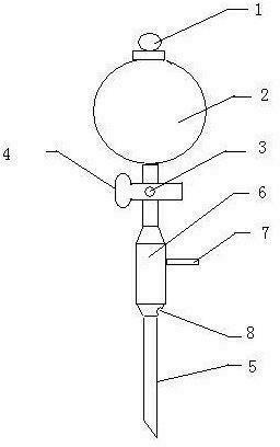
[0012] Such as figure 1 A separatory funnel, the separatory funnel comprises a plug 1, a spherical bucket body 2, a piston 3, a piston cavity 4 and a drain tube 5, the top of the drain tube 5 is connected to the spherical bucket body 2, and the piston cavity 4 is fixedly connected to the bottom of the drain tube 5 In the middle and upper part, the piston 3 is inserted into the piston cavity 4 and connected seamlessly with the piston cavity 4. A sleeve 6 is arranged on the outer side of the leakage tube 5 below the piston cavity 4. The sleeve 6 is flexibly connected with the leakage tube 5. The upper part of the sleeve 6 is provided with an air branch pipe. 7. An air inlet 8 is arranged on the lower wall of the casing 6 .

[0013] The piston chamber 4 is formed by fixed connection of two coaxial cylinders with different diameters, and the axis of the piston chamber intersects the drain pipe perpendicularly.

[0014] The diameter of the casing 6 is greater than that of the leak...


PUM

PropertyMeasurementUnit
Lengthaaaaaaaaaa
Lengthaaaaaaaaaa

Abstract

The invention provides a separatory funnel which comprises a stopper, a spherical funnel body, a piston, a piston chamber and a leaking pipe, wherein the top end of the leaking pipe is connected with the spherical funnel body, the piston chamber is fixedly connected with the middle upper part of the leaking pipe, the piston is inserted into the piston chamber and in a seamless flexible connection with the piston chamber, a sleeve is arranged on the outer side of the leaking pipe below the piston chamber, the sleeve is in a flexible connection with the leaking pipe, an air outlet branch pipe is arranged at the upper part of the sleeve, and an air inlet hole is formed on the wall of the lower opening of the sleeve. The separatory funnel has a simple structure and is easy to fabricate with low cost.

Description

technical field [0001] The invention relates to a separatory funnel for experiments, in particular to a separatory funnel with an air guiding device whose piston is not easy to drop. Background technique [0002] A separatory funnel is an experimental instrument commonly used in chemical experiments. In a gas generation experiment, it is necessary to assemble a gas generating device, an additive, an air guide tube and a separatory funnel. A general separatory funnel is composed of a bucket body and a drain tube. , there is a switch on the funnel. In the experiment of such a separating funnel, the stopper of the flask must be opened when adding the solution dropwise to the reactor. At this time, the poisonous substances and irritating substances are easy to volatilize, pollute the environment, and cause harm to the experimenter himself. It is also easy to cause health hazards, and during the experiment, it often occurs that the solution cannot be dripped continuously because ...

Claims


Application Information

Patent Timeline
IPC IPC(8): B01L3/00B67C11/00
Inventor 向阳项雨李海刚施鹏飞周海军
Owner NANJING JIAYE INSPECTION ENG
Why Eureka
Try Eureka