Spin coating device

A technology of spin coating agent and vacuum device, which is applied in the direction of surface coating liquid device, coating, photoplate making process coating equipment, etc., which can solve the problem of small specification range of processed products and difficulty in ensuring the consistency and thickness of film formation Improve the quality of the photosensitive film surface, reduce the number of foreign matter, and reduce the impact of problems such as poor uniformity

Active Publication Date: 2015-04-15
BOE TECH GRP CO LTD +1
View PDF6 Cites 3 Cited by
  • Summary
  • Abstract
  • Description
  • Claims
  • Application Information

AI Technical Summary

Problems solved by technology

The photosensitive adhesive film processed by silk screen has the following defects: 1) The photosensitive adhesive film layer is thicker, usually greater than 4um in thickness, and the thickness uniformity is poor. Usually, the 9-point test uniformity error (measured value of 9 points The ratio of the minimum value to the maximum value) is 60%-80%; 2) Since most of the silk screen printing methods are manual operations, it is difficult to ensure the consistency of film formation
However, even such a spin coating device has high equipment costs
Therefore, the spin coating equipment in the prior art has defects such as small specification range of processed products, light load, and high cost.

Method used


Image

  • Spin coating device
  • Spin coating device
  • Spin coating device

Examples


Embodiment Construction

[0040] The present invention embodies the structural features of the spin coating device of the present invention by describing the structure of the spin coating device in the following specific embodiments.

[0041] The content of the present invention will be described in further detail below in conjunction with the accompanying drawings. The same components are provided with the same reference numerals in the figures.

[0042] In the present invention, the workpiece spin-coated by the spin-coating device is a mold for manufacturing the light guide plate. In this specification, a mold with a thickness greater than 3mm is called a mold core or a mold core mold, and a mold with a thickness less than 3mm is called a thin-plate workpiece (STAMPER) or a thin-plate mold.

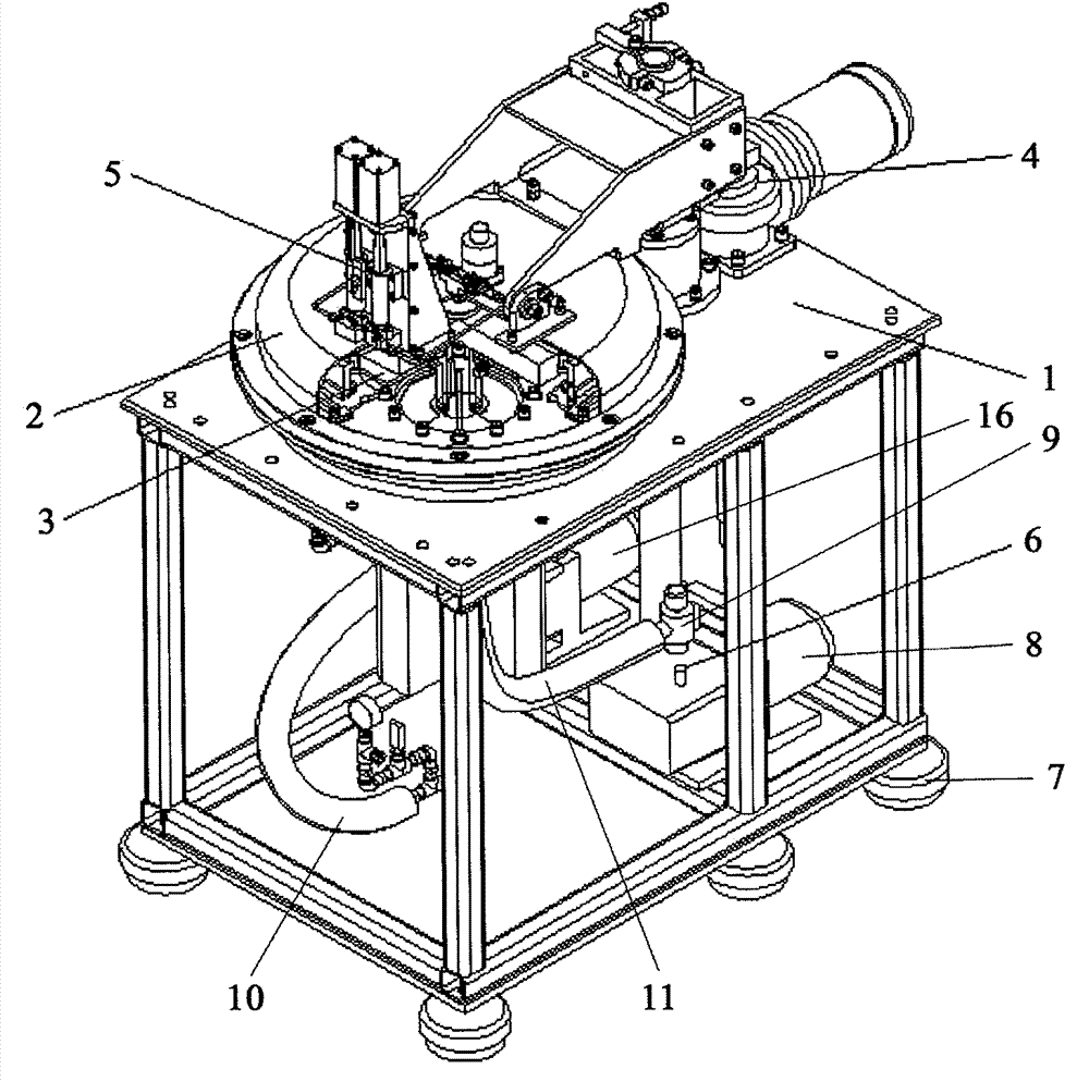
[0043]figure 1 is a schematic diagram of a spin coating device of a specific embodiment of the present invention installed on a stand. exist figure 1 Among them, the platform 1 is a basic component of the spi...


PUM


Abstract

The invention discloses a spin coating device. The spin coating device comprises a sealing cabin; a balance part installed in the sealing cabin; a mould clamp connected to the upper part of the balance part; a driving motor for driving the balance part and the mould clamp; a spin coating agent injecting device installed on the outer surface of the sealing cabin; a vacuum device for vacuumizing and de-vacuumizing the sealing cabin; and a balance detecting device which is electrically connected to the outer part of the spin coating device and used for detecting the balance of the entire spin coating device.

Description

technical field [0001] The present invention relates to the manufacture field of liquid crystal display, more particularly, the present invention relates to a kind of spin coating device, it is used for in the etching process of the light guide plate of liquid crystal display, the spin coating agent such as photosensitive glue etc. is evenly coated on the manufacturing light guide plate on the mold surface. Background technique [0002] In the liquid crystal display manufacturing industry, it is necessary to process the optical dots of the light guide plate (Light Guide Plate) used in the liquid crystal display, so as to realize the light guiding effect on the backlight source. In the prior art, when manufacturing the light guide plate, it is necessary to etch the mold (or mold core) for manufacturing the light guide plate. Before etching, the surface of the mold needs to be coated with a spin coating agent such as photosensitive glue. [0003] At present, the method of co...

Claims


Application Information

Patent Timeline
Patent Type & Authority Patents(China)
IPC IPC(8): B05C11/08B05C11/10B05C13/02G03F7/16G02F1/1333
Inventor 赵长春
Owner BOE TECH GRP CO LTD
Why Eureka
Try Eureka