Method for manufacturing copper-aluminum welded joint of capillary tube and copper end sleeved aluminum capillary tube

A technology for welding joints and capillaries, applied in the direction of pipes/pipe joints/fittings, welding equipment, welding/welding/cutting items, etc. The effect of reducing the number of

Active Publication Date: 2012-09-19
左铁军 +1
View PDF4 Cites 7 Cited by
  • Summary
  • Abstract
  • Description
  • Claims
  • Application Information

AI Technical Summary

Problems solved by technology

[0003] Capillary is a kind of pipeline with relatively thin inner diameter. At present, copper tubes with an inner diameter of 0.5-0.7mm are used in the refrigerator industry; copper tubes with an inner diameter of 0.7-2.0mm are used in the air-conditioning industry. Due to the small inner diameter of the capillary, welding spatter will If the pores are blocked and cannot be removed, it cannot be completed by friction welding, energy storage welding, flash butt welding and other welding methods that are prone to spatter; the brazing method of flared connection needs to be socketed at one end of the connecting pipe. , the thin diameter exceeds 20mm to ensure that there is no welding blockage, and the thin diameter deep flaring cannot be realized, so brazing cannot complete the welding of thin diameter copper-aluminum tubes. For the same reason, the brazing method cannot complete the copper capillary connected by flaring. Or aluminum capillary tube, in summary, the current technology cannot realize capillary copper-aluminum tube welding
[0004] The existing sleeve extrusion resistance welding technology adopts the method of inserting copper tubes into aluminum tubes for welding and flaring after welding. Although a dense pipeline joint structure can be obtained, the inner diameter of copper-aluminum pipe fittings suitable for this welding method must be Greater than 2.0mm, the inner diameter of the capillary is less than 2.0mm, the above method cannot realize the copper-aluminum welding of the capillary

Method used


Image

  • Method for manufacturing copper-aluminum welded joint of capillary tube and copper end sleeved aluminum capillary tube
  • Method for manufacturing copper-aluminum welded joint of capillary tube and copper end sleeved aluminum capillary tube
  • Method for manufacturing copper-aluminum welded joint of capillary tube and copper end sleeved aluminum capillary tube

Examples


Embodiment Construction

[0023] A preparation method for a capillary copper-aluminum welded joint, comprising the steps of:

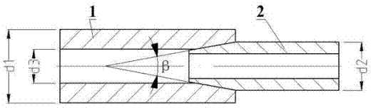
[0024] (1) A high-temperature-resistant rod-shaped inner core that is harder than the copper capillary and exposed at both ends of the copper capillary is preset inside the copper capillary. The diameter of the inner core is smaller than the inner diameter of the aluminum capillary;

[0025] (2) Use a precision roll forging machine to taper one end of the copper capillary, and reduce the wall thickness of the copper capillary to form a welding surface with a certain taper taper b. At this time, the copper capillary shrinks in the inner diameter of the welding surface area, and the inner diameter after shrinkage is not smaller than the diameter of the inner core, and the inner core is stuck at the cone head;

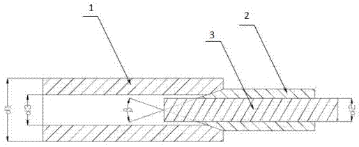
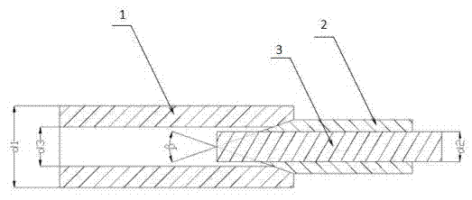
[0026] (3) if figure 1 Pre-assembled by inserting the tapered end of the copper capillary with the inner core into the aluminum capillary as shown;

[0027] (4) Place th...


PUM


Abstract

The invention relates to a method for manufacturing a copper-aluminum welded joint of a capillary tube, and a copper end sleeved aluminum capillary tube which is manufactured by the method. The method comprises the following steps of inserting a core into a copper tube, wherein the core is exposed from two ends of the copper tube; one end of the copper tube is made to be a conical head by a precise roller forging machine, and thinning the wall of the copper tube, so that the core is clamped at the conical head; preassembling the conical end of the copper capillary tube with the core into an aluminum tube; and welding and pulling the core out. Gaps in contact parts of the copper tube and the aluminum tube are small, so that an aluminum bead cannot be generated, and the flow of the capillary tube cannot be influenced.

Description

technical field [0001] The invention relates to a method for preparing a welded joint, in particular to a method for preparing a capillary copper-aluminum welded joint; the invention also relates to a sleeve-type copper-end aluminum capillary prepared by the method. Background technique [0002] At present, copper resources are in short supply, but the performance of aluminum is the closest to that of copper, and the output is abundant. Therefore, replacing copper tubes with aluminum tubes has become one of the most effective means for saving copper resources and reducing product manufacturing costs in the refrigeration industry. The scale of replacing copper with aluminum in refrigeration products is also increasing. In the refrigeration system, evaporators, return air pipes, condensers, dew pipes, and piping in the system have successively realized aluminum instead of copper. Capillary tubes are an essential system function for refrigeration products. One of the components...

Claims


Application Information

Patent Timeline
IPC IPC(8): B23K11/00B23K11/34F16L9/02F16L13/02F16L13/007
CPCB23K11/00B23K11/34B23K33/006B23K2203/18F25B41/067F16L13/02F16L13/007F16L9/02B23K2103/10B23K2103/12B23K2103/18F25B41/37
Inventor 赵越左铁军杨训孙德兴姜祺祥史晓霞石志德袁超王昕王岩
Owner 左铁军
Why Eureka
Try Eureka