
Composite wheel structure automobile

A wheel and car technology, applied in the direction of wheels, wheels that can support multiple tires, vehicle parts, etc., can solve the problems of energy waste, low efficiency, and high energy consumption of vehicles

Inactive Publication Date: 2017-09-12
尚久駜 +1
View PDF7 Cites 0 Cited by
  • Summary
  • Abstract
  • Description
  • Claims
  • Application Information

AI Technical Summary

Problems solved by technology

The principle of classical wheel kinematics reveals that in this traditional wheel system structure, the larger the radius of the driven wheel, the smaller the required thrust, and the smaller the radius of the driving wheel, the greater the driving force. The wheel radii of these two different functions The orientation is opposite. Therefore, all the current methods of designing the wheel system with the same radius are not advisable; in addition, the driving wheel structure of this traditional concept has dual functions of loading and driving, just like pulling a cart with a heavy load. Please... The current situation of the road vehicle wheel system structure is an important reason for the high energy consumption and low efficiency of the vehicle. These disadvantages are not recognized enough and people are still wantonly creating many Vehicles with laborious driven wheels and weak driving wheels supply the ever-increasing demand, resulting in huge waste of energy and invisible disasters for social development

Method used


Image

  • Composite wheel structure automobile
  • Composite wheel structure automobile
  • Composite wheel structure automobile

Examples


Embodiment Construction

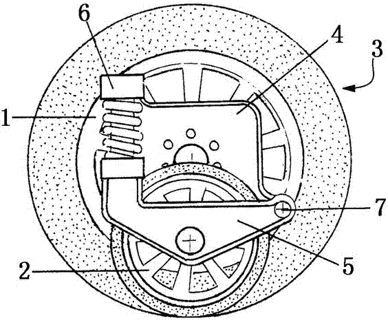
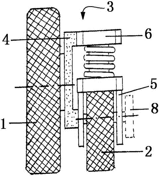
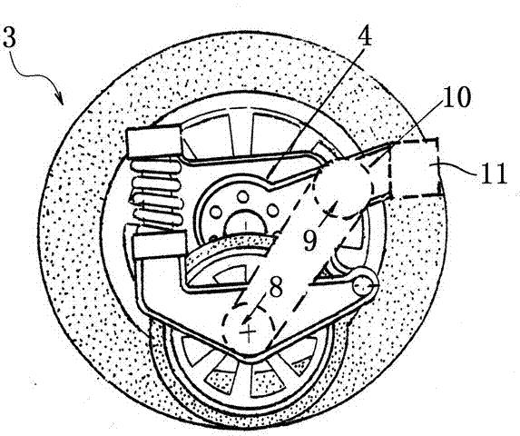
[0027] see figure 1 and figure 2 , the composite wheel 3 is based on the load wheel 1, and the non-load wheel (drive wheel) 2 is auxiliary, and is combined through connecting parts. Its composition is:

[0028] The load wheel 1 is fixed on the connecting bracket 4, and the connecting bracket 4 is connected with the vehicle body to form a stable wheel structure system;

[0029] The non-load wheel (drive wheel) 2 is fixed by the movable bracket 5, one end of the movable bracket 5 is connected to the pressure regulator 6, and the other end of the pressure regulator 6 is connected to the connecting bracket 4; the other end of the movable bracket 5 is fixed on the connecting bracket 4 through the movable joint 7 On the top, a composite overall structure of the non-load wheel (drive wheel) 2 flexibly accompanied by the load wheel 1 is formed;

[0030] The non-load wheel (drive wheel) 2 of the composite wheel 3 is connected with the external power transmission system through the ...


PUM


Abstract

The invention discloses an automobile with a composite wheel structure, belonging to the field of automobile manufacturing and aiming to solve the problems of the traditional automobiles of small automobile drive force and high energy consumption caused by internal contradicts of a wheel system structure, double functions of loading and driving of a drive wheel structure and larger wheel radius. The automobile with a composite wheel structure comprises a connecting bracket connected with an automobile axle and composite wheels consisting of a loading wheel and a non-loading wheel, wherein the connecting bracket is fixedly connected with the loading wheel; the connecting bracket is also connected with a mobile bracket, the non-loading wheel is arranged on the mobile bracket, and the mobile bracket is hinged on the connecting bracket; the non-loading wheel is connected with an external power transmission system through a drive joint; and the radius of the non-loading wheel is smaller than or equal to the half of the radius of the loading wheel. The purposes of greatly improving the automobile drive force and greatly saving energy are achieved by the automobile with the composite wheel structure on the premise of not increasing original power configurations of the automobile.

Description

technical field [0001] The invention relates to the field of automobile manufacturing, in particular to an automobile with a compound wheel structure. Background technique [0002] At present, the widely used automobile wheel system structure is the concept of driven wheel and driving wheel structure. It is a system of driven wheels and driving wheels with equal radii. In this system, the wheels that rely on the torque transmitted to the circumference of the wheel are called The driving wheel, the wheel that relies on the thrust of the center of the wheel to roll is called the driven wheel. The principle of classical wheel kinematics reveals that in this traditional wheel system structure, the larger the radius of the driven wheel, the smaller the required thrust, and the smaller the radius of the driving wheel, the greater the driving force. The wheel radii of these two different functions The orientation is opposite. Therefore, all the current methods of designing the whe...

Claims


Application Information

Patent Timeline
Patent Type & Authority Patents(China)
IPC IPC(8): B60B11/02
Inventor 尚久駜李立衡
Owner 尚久駜
Learn More