Stacking machine

A palletizer and deceleration motor technology, which is applied in the field of palletizers, can solve the problems of palletizer transfer mechanism wear, block breakage, etc., and achieve the effect of not being easily damaged

Active Publication Date: 2012-09-19
山东未来城建筑工程有限公司
View PDF9 Cites 44 Cited by
  • Summary
  • Abstract
  • Description
  • Claims
  • Application Information

AI Technical Summary

Problems solved by technology

[0004] In order to overcome the problems that the existing palletizers easily cause block breakage, edge drop, missing corners and easy to wear the transfer mechanism of the palletizer, the present invention provides a palletizer capable of protective palletizing, which ensures production Under the required conditions, no damage to the block

Method used


Image

  • Stacking machine
  • Stacking machine
  • Stacking machine

Examples


Embodiment Construction

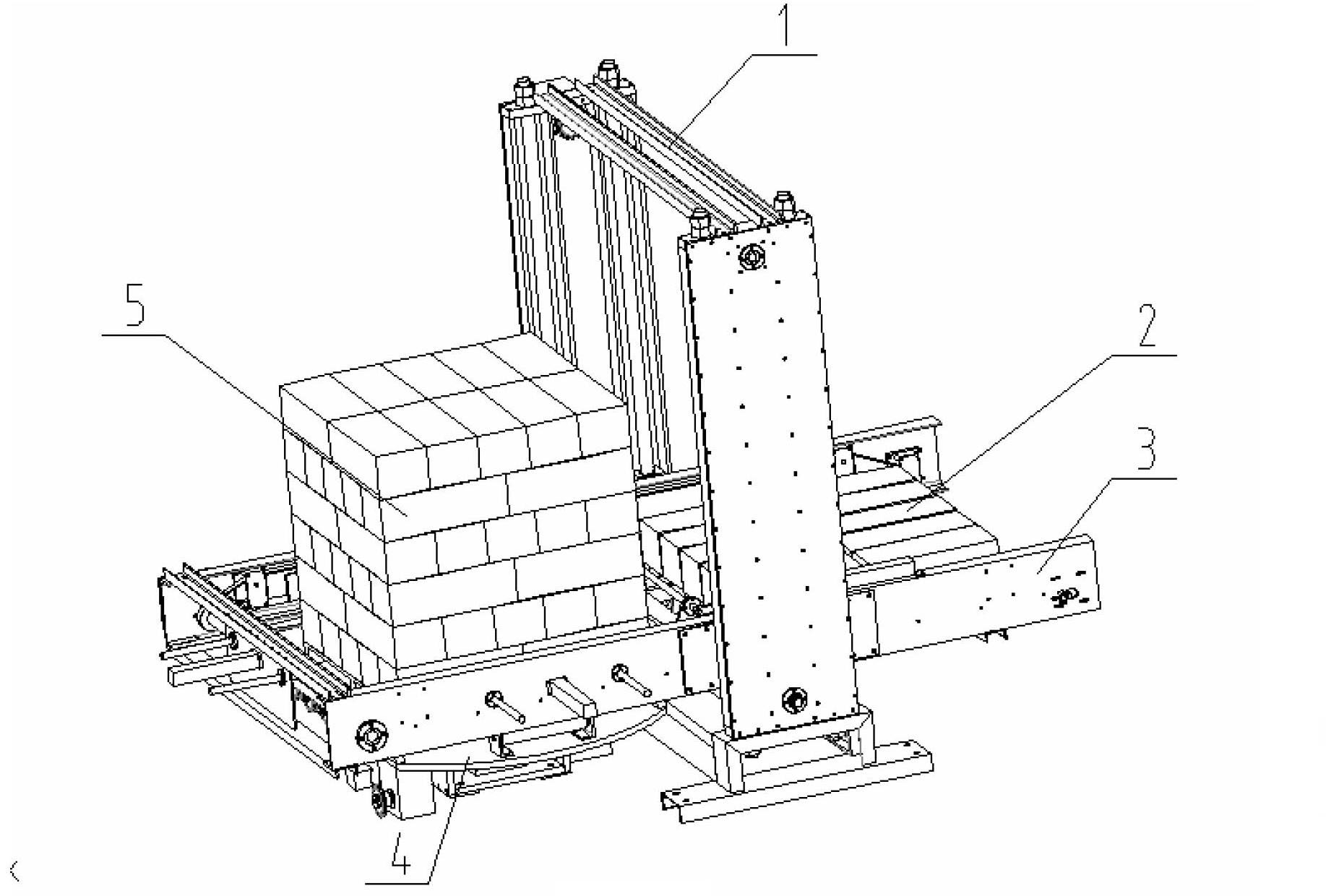
[0040] refer to Figure 1 to Figure 15 , a palletizer, including a lifting traction device 1, a lifting device 3, a stacking device 2 and a stacking rotary table 4; the lifting traction device 1 is connected to the lifting device 3 by transmission, and the stacking device 2 Move within the lifting device 3; one side of the stack pushing device 2 is provided with the stack supporting rotary table 4;

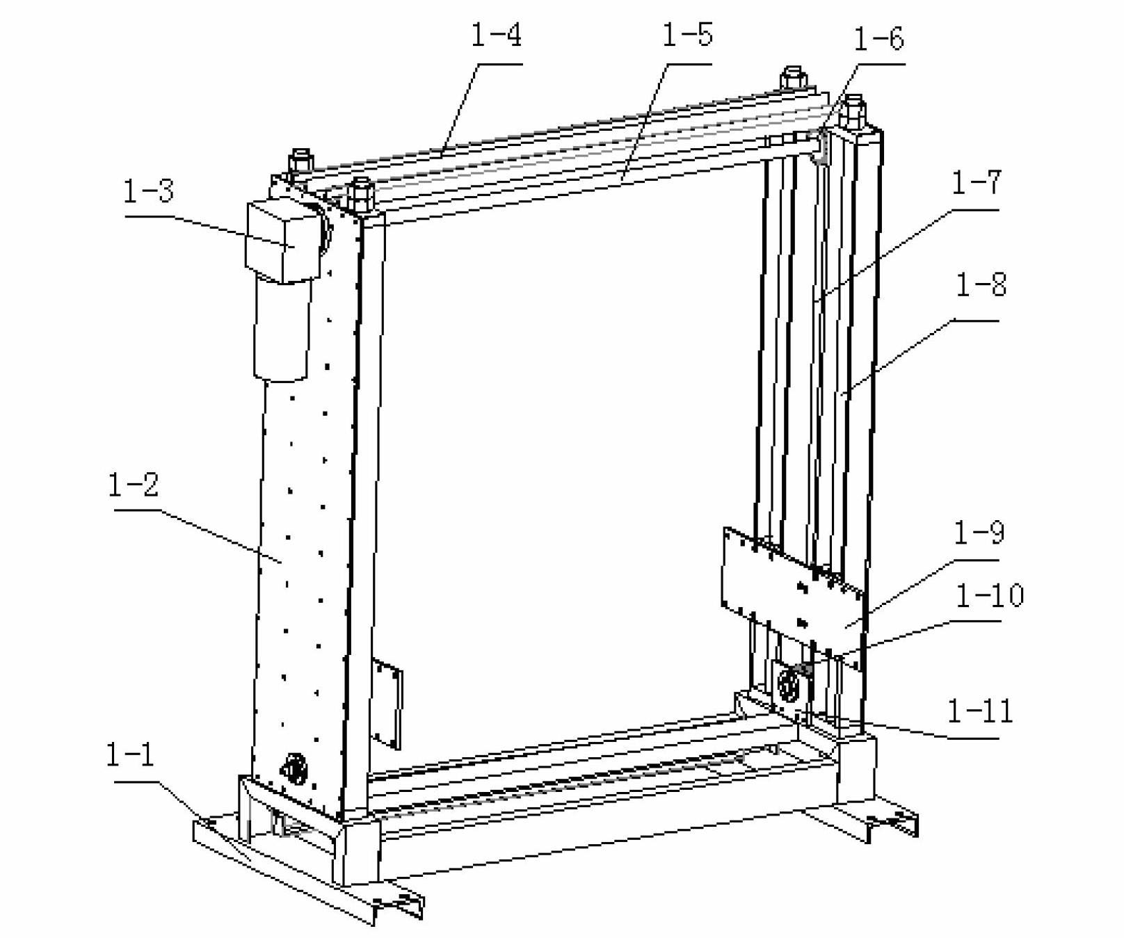
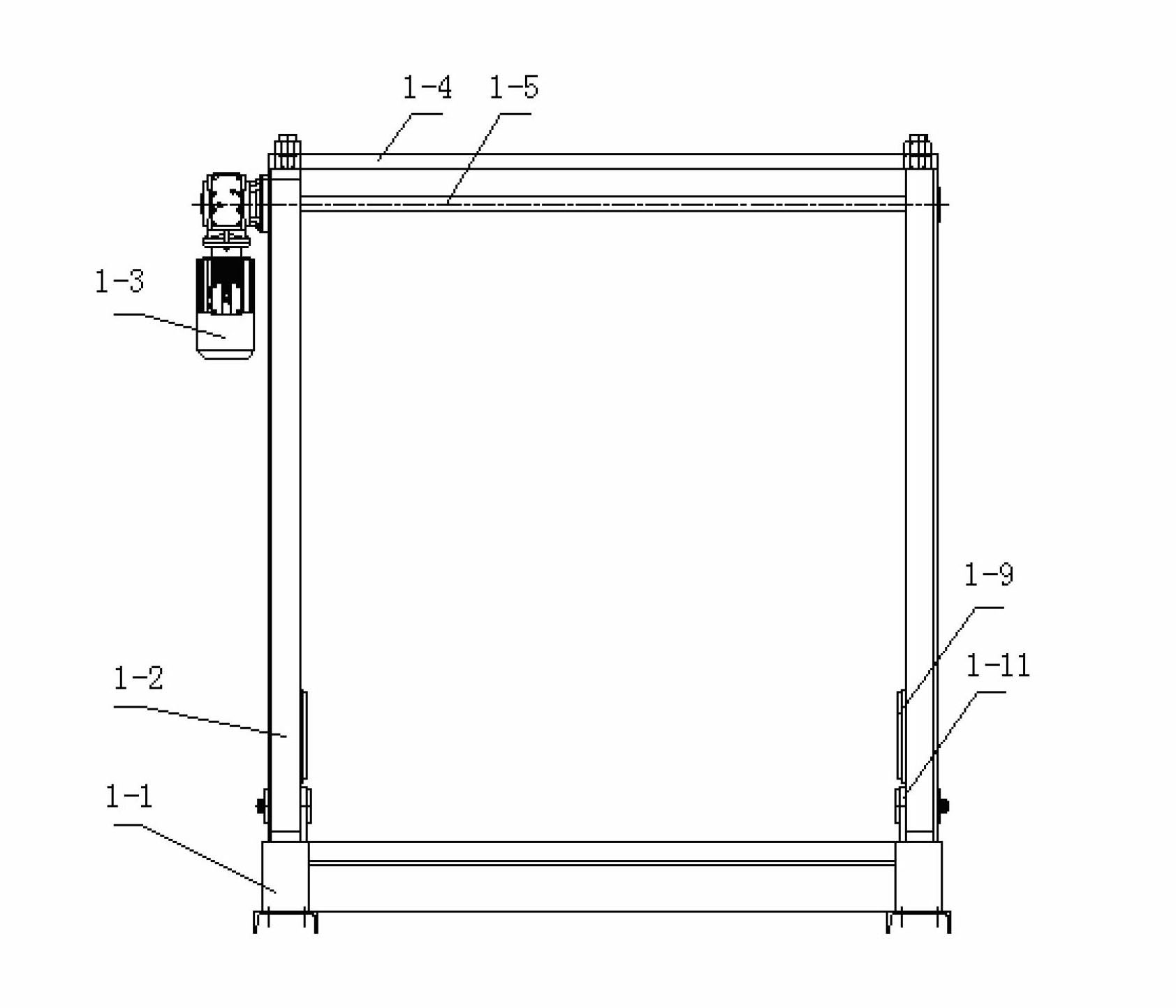
[0041]The lifting traction device 1 includes a lifting traction frame 1-1, a column 1-2, a geared motor 1-3, a beam 1-4, a drive shaft 1-5, a driving sprocket 1-6, a chain 1-7, a guide Column 1-8, guide sleeve 1-12, lifting device installation connecting plate 1-9 and tensioning sprocket 1-10, one end of the column 1-2 is respectively connected to both sides of the lifting traction frame 1-1; The other end is connected with the beam 1-4 to form a gantry structure; the geared motor 1-3 is installed on the upper side of the column 1-2 on one side, and one end of the drive shaft 1-5...


PUM


Abstract

The invention discloses a stacking machine which comprises a lifting traction device, a lifting device, a stack pushing device and a stack-bearing rotary operating platform. The lifting traction device is in transmission connection with the lifting device, and the stack pushing device moves in the lifting device; the stack-bearing rotary operating platform is arranged at one side of the stack pushing device; the lifting traction device comprises a lifting traction frame, vertical posts, a speed reducing motor, cross beams, driving shafts, driving chain wheels, chains, guide posts, guide sleeves, lifting device mounting and connecting plates and tension chain wheels; the lifting device comprises a lifting framework, a driving shaft, a driving synchronous pulley, a stack pushing motor, a shaping and clamping device, a material baffling mechanism, the stack pushing device, a synchronous belt, a synchronous belt tension wheel and a synchronous belt connecting seat; and the stack-bearing rotary operating platform comprises a base, a rotary platform, a rotary motor, a worm and worm-wheel transmission case, a conveying motor and a roller conveyor. When the stacking machine is arranged on a conveying line, building blocks are difficult to damage under the condition of guaranteeing the production requirements.

Description

technical field [0001] The invention relates to a palletizer. Background technique [0002] At present, there are mainly high-position automatic palletizers, low-position automatic palletizers and manipulator automatic palletizers on the market. The high-position and low-position automatic palletizers are suitable for the palletizing of packaged items. The packaging boxes are arranged on the conveyor line according to the palletizing requirements, and the materials are transported to the palletizing mechanism through the transfer mechanism for palletizing. The manipulator palletizer clamps the palletized items from the conveyor line through the manipulator, and places the materials on the pallet for palletizing according to the palletizing requirements. [0003] Ceramsite self-reinforced aerated block is a new type of wall material made of fly ash, lightweight ceramsite, cement, etc., through foaming, curing, and cutting. In the production process, because the solidificati...

Claims


Application Information

Patent Timeline
Patent Type & Authority Applications(China)
IPC IPC(8): B65G57/10
Inventor 秦宝荣赵海宝王淑花韩立光
Owner 山东未来城建筑工程有限公司
Why Eureka
Try Eureka