
Double-shaft needling machine

A shaft needle and main shaft technology, applied in the field of double shaft needle punching machines, can solve the problems of increasing noise, affecting the transmission effect, trouble, etc., and achieving the effect of reducing the difficulty of manufacturing and installation, shortening downtime, and reducing the cost of use

Inactive Publication Date: 2012-09-19
常熟市伟成非织造成套设备有限公司
View PDF9 Cites 43 Cited by
  • Summary
  • Abstract
  • Description
  • Claims
  • Application Information

AI Technical Summary

Problems solved by technology

[0004] The biaxial needle loom with the above structure is commonly used by manufacturers of non-woven products at present, but there are the following technical problems: First, the noise is large, which is harmful to on-site work. environment, because the movement of the auxiliary shaft is realized by driving the auxiliary shaft gear fixed on the main shaft through the main shaft gear fixed on the main shaft, and the meshing movement between the main and auxiliary shaft gears will generate serious noise; 1. The secondary shaft gear wears after a period of use, so it not only increases the noise, but also affects the transmission effect. However, it is more troublesome when replacing the main and secondary shaft gears; third, because the main and secondary shafts are integral Structure, that is, the length of the main and auxiliary shafts is adapted to the maximum width (width) of the processed non-woven fabric, so when the bearings on the bearing seats used to support the main and auxiliary shafts are to be maintained or even replaced , the time spent usually takes one to two days, which affects the working efficiency of the needle loom; Fourth, once the main shaft and / or auxiliary shaft are damaged, they can only be replaced as a whole, which wastes resources and increases the cost of use

Method used


Image

  • Double-shaft needling machine
  • Double-shaft needling machine
  • Double-shaft needling machine

Examples


Embodiment Construction

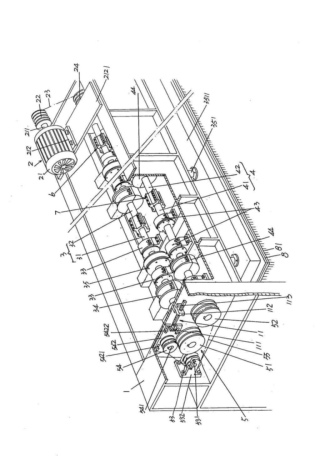
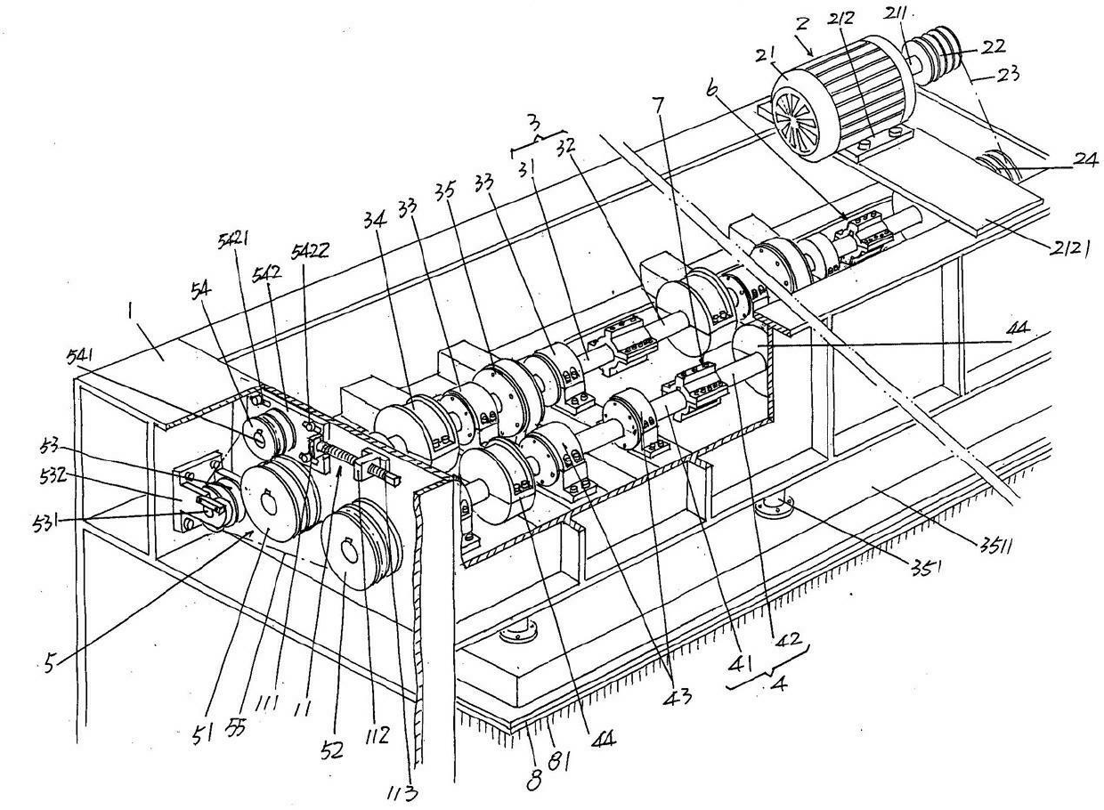
[0018] In order to enable the examiners of the patent office, especially the public, to understand the technical essence and beneficial effects of the present invention more clearly, the applicant will describe in detail the following in the form of examples, but none of the descriptions to the examples is an explanation of the solutions of the present invention. Any equivalent transformation made according to the concept of the present invention which is merely formal but not substantive shall be regarded as the scope of the technical solution of the present invention.

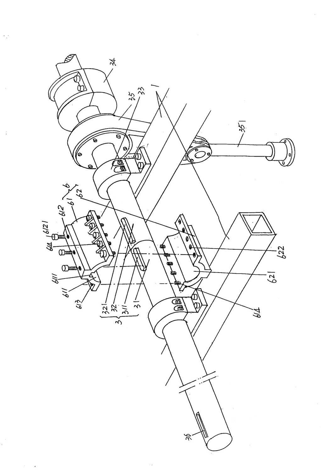
[0019] See figure 1 , the frame 1 of the double-axis needle loom is given, and one end at the top of the frame 1 is figure 1 The right end of the shown position state is provided with a power transmission mechanism 2, and a main shaft 3 and a secondary shaft 4 are rotatably arranged on the top of the frame 1, specifically, the main shaft 3 is rotatably supported in a horizontal state by a main shaft be...


PUM


Abstract

The invention discloses a double-shaft needling machine, belonging to the technical field of non-woven textile machinery. The machine comprises a rack, a power transmission mechanism, a main shaft, an auxiliary shaft and an auxiliary shaft transition transmission mechanism. The machine is characterized in that the auxiliary shaft transition transmission mechanism comprises a first belt wheel, a second belt wheel, a transition belt wheel, a tension belt wheel and a transmission belt, wherein the first belt wheel is fixed at the other end part of the main shaft; the second belt wheel is fixed on the auxiliary shaft and corresponds to the first belt wheel; the transition belt wheel and the tension belt wheel are arranged on the rack; the transmission belt is sleeved on the first and second belt wheels, the transition belt wheel and the tension belt wheel; and the transition belt wheel, the tension belt wheel and the first belt wheel are in a triangular positional relation. The double-shaft needling machine disclosed by the invention has the advantages of avoiding noise, reducing the manufacturing and mounting difficulty, being beneficial to maintaining and replacing a bearing, shortening the shutdown time, ensuring the operation efficiency, saving resources and lowering the cost.

Description

technical field [0001] The invention belongs to the technical field of non-woven machinery, and in particular relates to a double-axis needle punching machine. Background technique [0002] The so-called double-axis acupuncture machine means that in addition to the main shaft (called the main drive shaft in the industry), it also has a secondary shaft parallel to the main shaft (called the balance shaft in the industry). The acupuncture machine with this structure can meet the requirements of high-speed acupuncture. Improve the output of non-woven fabrics such as non-woven fabrics and non-woven felts per unit time. [0003] The sub-shaft of the double-axis acupuncture machine is rotated by the meshing of the main shaft gear on the main shaft and the counter shaft gear on the sub-shaft, and the main shaft is driven by the power transmission mechanism arranged on the frame. Specifically, as the power transmission mechanism works, it drives the main shaft connected to it and r...

Claims


Application Information

Patent Timeline
IPC IPC(8): D04H18/02
Inventor 王卫成郑耀华
Owner 常熟市伟成非织造成套设备有限公司
Learn More