Material raking and breaking and surface cleaning loader
A loader and raking technology, which is applied in the fields of mine excavation, mining, and tunnel excavation, can solve the problems of uneven loading, difficult loading, and large space occupation
- Summary
- Abstract
- Description
- Claims
- Application Information
AI Technical Summary
Problems solved by technology
Method used
Image
Examples
Embodiment 1
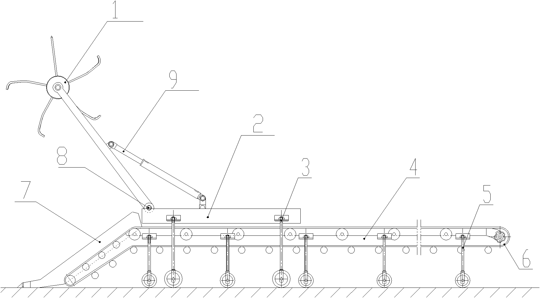
[0038] figure 1It is the raking material breaking surface clearing loader described in this embodiment. The loader includes a raking mechanism and a material guiding device. The raking mechanism includes a hobbing rake device 1 and a rolling rake frame 2. During operation, the hobbing rake device 1 is located in front of, above or above the front of the material guiding device. The hobbing tooth raking device 1 may only include the rake cylinder, or only the rake shaft, or both the rake cylinder and the rake shaft. At this time, the rake cylinder is sleeved on the rake shaft. There is at least one row of rake teeth on the outer surface of the rake shaft or the rake cylinder. When multiple rows of rake teeth are provided, each row of rake teeth is arranged at intervals radially along the surface of the rake shaft or the rake cylinder. The hobbing rake device 1 is arranged on the rake frame 2, and the rake shaft and / or drum of the hobbing rake device 1 are connected to the rak...
Embodiment 2
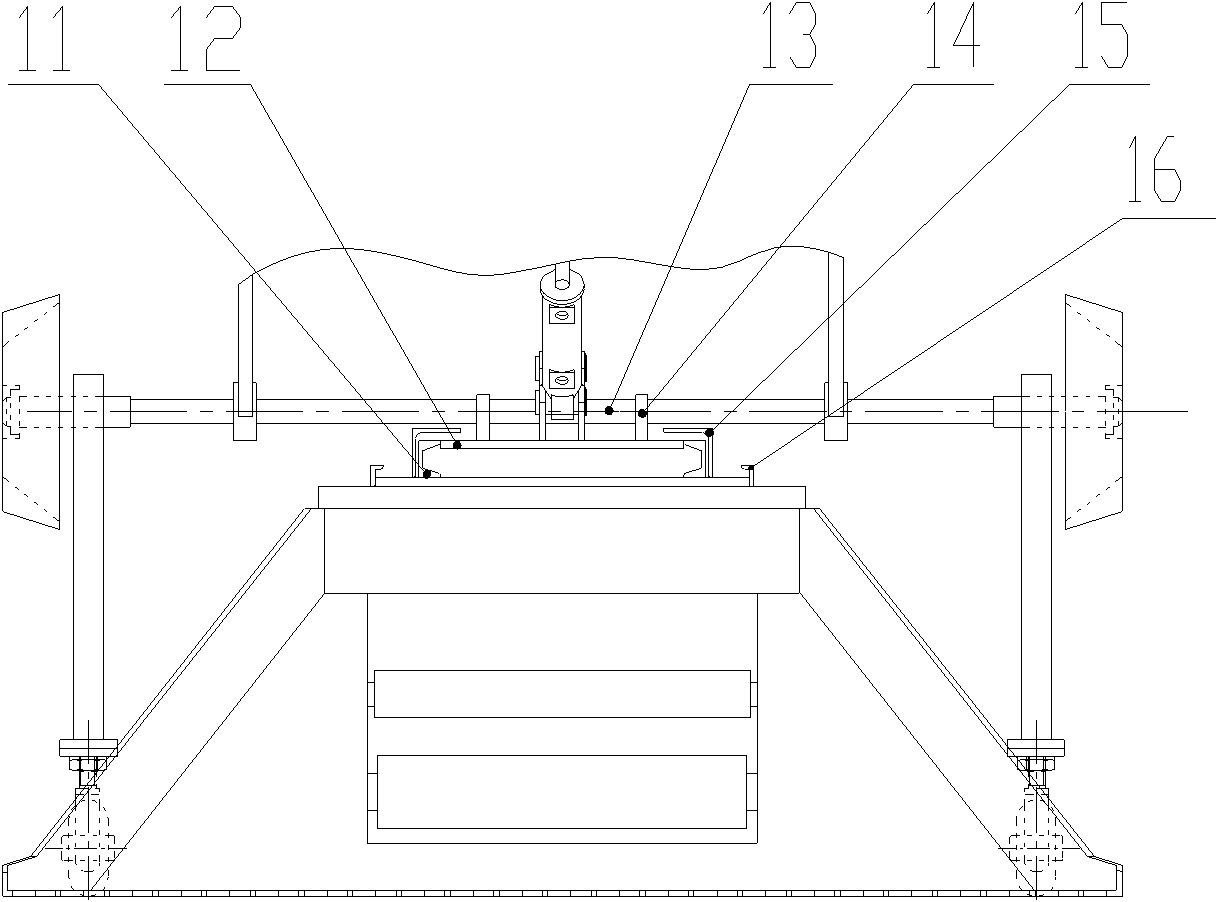
[0046] figure 2 and image 3 It is the raking material breaking surface clearing loader described in embodiment 2. The difference from Embodiment 1 is that the raking mechanism in this embodiment includes a pick-tooth raking device 10, which includes a rake shaft and / or a rake drum, and is radially spaced along the outer circumferential surface of the rake shaft or rake drum At least one row of rake tines, rake tines, rake hammers and rake plates. The rolling pick teeth raking device 10 is fixed on the rolling rake frame 2, and the bottom of the rolling rake frame 2 is not provided with the rolling rake frame walking wheel 3. The rake frame 2 includes channel steel 11 and steel plate 12 . The material guiding device is provided with a support plate, on which a pair of guide angle steels 15 are fixed along the conveying direction of the belt conveyor, and these two relative guide angle steels 15 form guide rails. The inner sides of the two guide angles 15 are respectively ...
Embodiment 3
[0049] Figure 4 to Figure 6 It is the raking material breaking surface clearing loader described in embodiment 3. The difference from Embodiment 1 is that the raking mechanism used in this embodiment includes a scraper tooth chain raking device 18, one end of the scraper tooth chain raking device 18 is connected with the rolling rake frame 2 through the rotating shaft 13, and the rolling rake The frame 2 includes channel steel 11 and steel plate 12 . The rotating shaft 13 can drive the scraper tooth chain raking device 18 to rotate up and down. The other end of the scraper tooth chain raking device 18 is a discharge end, which can be flexibly connected or fixedly connected with the material guiding device. The material guiding device includes a frame 17, and the left and right sides of the frame are respectively fixed with adjustment oil cylinders 9. One end of the left and right adjustment oil cylinder 9 is connected with the bearing II 20 fixed on the frame 17, and the o...
PUM
 Abstract
Description
Claims
Application Information
 - R&D
- Intellectual Property
- Life Sciences
- Materials
- Tech Scout
- Unparalleled Data Quality
- Higher Quality Content
- 60% Fewer Hallucinations
Browse by: Latest US Patents, China's latest patents, Technical Efficacy Thesaurus, Application Domain, Technology Topic, Popular Technical Reports.
© 2025 PatSnap. All rights reserved.Legal|Privacy policy|Modern Slavery Act Transparency Statement|Sitemap|About US| Contact US: help@patsnap.com


