
Engine

A technology for engines and cylinder blocks, which is applied in the direction of engine components, machines/engines, mechanical equipment, etc. It can solve problems such as cylinder deformation, slow water flow, and poor cooling effect of the cylinder head, and achieve enhanced cooling strength, shortened flow distance, good cooling effect

Active Publication Date: 2012-09-19
GREAT WALL MOTOR CO LTD
View PDF5 Cites 19 Cited by
  • Summary
  • Abstract
  • Description
  • Claims
  • Application Information

AI Technical Summary

Problems solved by technology

[0004] Since the water jacket on the intake side of the cylinder body is integrally connected to the water jacket on the exhaust side of the cylinder body, the cooling water enters the water jacket of the cylinder body from the water inlet on one side of the cylinder body, and has to flow through the entire water jacket of the cylinder body to realize the cooling around the cylinder. Cooling, in this way, the water flow velocity in the area far from the water inlet is slow and easy to form a dead water area, resulting in uneven cooling, and the cylinder is prone to deformation risks due to uneven heating; and because the water jacket on the intake side of the cylinder and the water on the exhaust side The jacket is connected as a whole, and the water circulation in the engine flows from the cylinder block to the cylinder head, so the cooling water entering the cylinder head water jacket is a high-temperature water flow after absorbing the heat of the cylinder block, and the cooling effect on the cylinder head is relatively poor.

Method used


Image

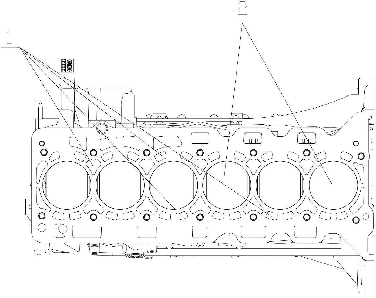
  • Engine
  • Engine
  • Engine

Examples


Embodiment Construction

[0018] It should be clear that the described embodiments are only some of the embodiments of the present invention, not all of them. Based on the embodiments of the present invention, all other embodiments obtained by persons of ordinary skill in the art without creative efforts fall within the protection scope of the present invention.

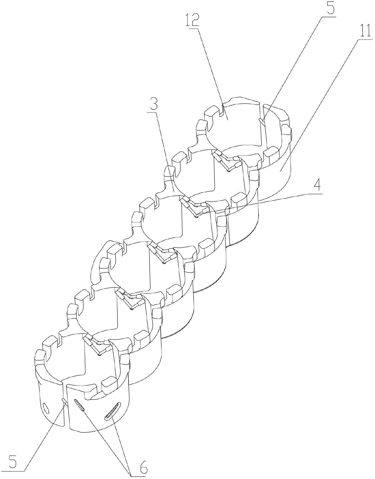
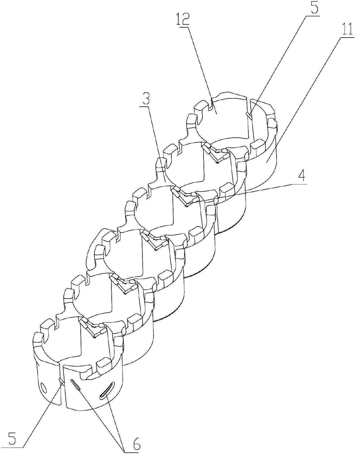
[0019] The engine provided by the embodiment of the present invention includes a cylinder block and a cylinder head, the cylinder head is covered on the cylinder block, wherein the cylinder block is provided with a plurality of cylinder barrels, and the cylinder barrels are used to realize the mixing of oil and gas and Combustion and release heat, so the surroundings of the cylinder barrel and the cylinder head are the areas that bear the highest heat, and the cooling system of the engine is mainly to cool the surroundings of the cylinder barrel and the cylinder head. Therefore the following combines figure 1 with figure 2 The cooling syst...


PUM


Abstract

The embodiment of the invention discloses an engine, relates to the technical field of automobiles and aims at improving the cooling effect of the engine. The engine comprises a cylinder body, a cylinder cover is covered on the cylinder body, a plurality of cylinder barrels and a cylinder body water jacket around the cylinder barrels are arranged on the cylinder body, the cylinder body water jacket is arranged on the cylinder cover, and the cylinder body water jacket comprises a water jacket on the air inlet side of the cylinder body and the water jacket on the exhaust side of the cylinder body, wherein the water jacket on the air inlet side of the cylinder body and the water jacket on the exhaust side of the cylinder body are mutually isolated, a water inlet is further arranged on the water jacket on the exhaust side of the cylinder body, a water outlet is arranged on the water jacket on the air inlet side of the cylinder body, and cooling water can enter into the water jacket on the exhaust side of the cylinder body from the water inlet, further enter into the cylinder cover water jacket from the water jacket on the exhaust side of the cylinder body, then enter into the water jacket on the air inlet side of the cylinder body from the cylinder cover water jacket and finally flow out of the water outlet. The engine disclosed by the invention is used for cooling the periphery of the cylinder barrels of the engine.

Description

technical field [0001] The invention relates to the technical field of automobiles, in particular to an engine. Background technique [0002] With the development of automobile technology, many new technologies are applied to automobile engines, so that the power of the engine is continuously increased, and the heat load of the engine is also getting higher and higher. The quality of the engine cooling system is directly related to the life of the engine. A poor cooling system can easily cause engine damage. [0003] The engine cooling system mainly includes the engine water supply system and the engine cooling water jacket structure. The engine cooling water jacket structure is composed of the cylinder block water jacket and the cylinder head water jacket. The cylinder block water jacket includes the cylinder block intake side water jacket and the cylinder block exhaust side. Water jacket, and the water jacket on the intake side of the cylinder block is integrally connecte...

Claims


Application Information

Patent Timeline
IPC IPC(8): F02F1/16F02F1/14
Inventor 张堪想张文德赵国东林文闫立虎杨日升
Owner GREAT WALL MOTOR CO LTD
Learn More