Diagnostic method for carbon canister flow

A diagnostic method and technology of carbon canisters, applied in the direction of adding non-fuel substances, engine components, machines/engines, etc.

Active Publication Date: 2012-09-19
UNITED AUTOMOTIVE ELECTRONICS SYST
View PDF4 Cites 22 Cited by
  • Summary
  • Abstract
  • Description
  • Claims
  • Application Information

AI Technical Summary

Problems solved by technology

[0017] The technical problem to be solved in this application is to provide a diagnostic method for the flow rate of the canister in the evaporative emission control system of the automobile engine, so as to overcome the shortcomings of the existing diagnostic methods such as unreliability and complicated diagnostic process

Method used


Image

  • Diagnostic method for carbon canister flow
  • Diagnostic method for carbon canister flow
  • Diagnostic method for carbon canister flow

Examples


no. 1 example

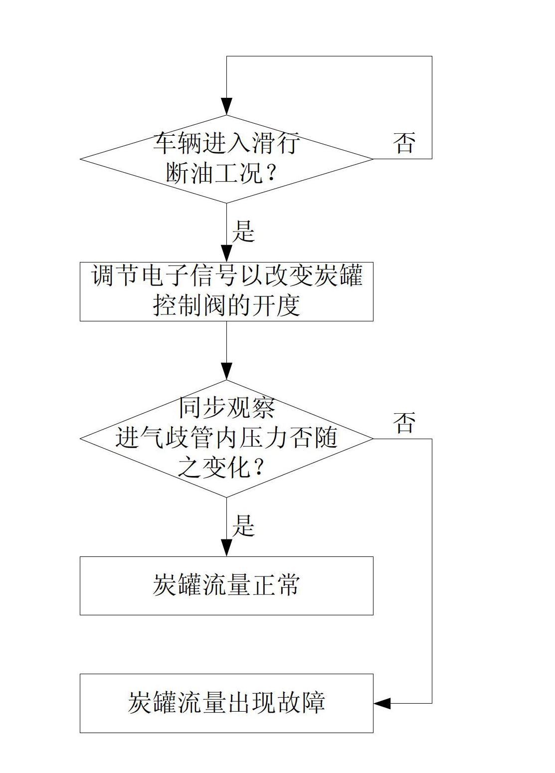
[0029] see figure 2 , the first embodiment of the method for diagnosing the canister flow of the present application includes:

[0030] First, the EMS system waits for the vehicle to enter the coasting fuel cut-off condition. The coasting fuel cut-off condition means that the vehicle satisfies the following three conditions at the same time: the vehicle has a certain speed (>0), the fuel injection device does not inject fuel, and the throttle valve is fully closed.

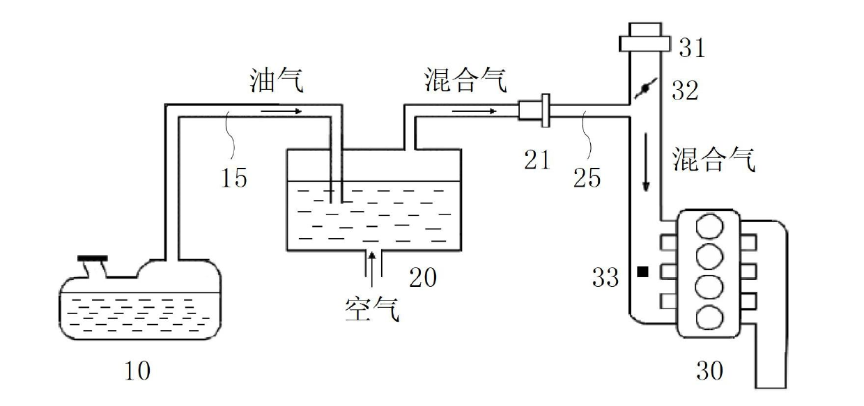
[0031] Then, the EMS system adjusts the electronic signal controlling the opening of the canister control valve 21 and simultaneously detects the pressure in the intake manifold 30 . Normally, the opening degree of the canister control valve 21 is controlled by electronic signals to change. For example, the electronic signal is a PWM signal, and the opening of the canister control valve 21 is linearly proportional to the duty cycle of the PWM signal. As the duty ratio of the PWM signal increases, the opening o...


PUM


Abstract

The invention discloses a diagnostic method for carbon canister flow. The diagnostic method comprises the following steps of: when a vehicle enters into a slide fuel-cut operating mode, adjusting and controlling an electronic signal for an opening of a carbon canister control valve by an engine managing system so as to change the opening of the carbon canister control valve, and synchronously detecting if the change speed of the pressure in an induction manifold changes following the change of the opening; if yes, confirming that the carbon canister flow is normal; and if not, confirming that the carbon canister flow is in fault. According to the diagnostic method for the carbon canister flow, the tightly blocking or pipeline blocking fault of the carbon canister control valve is effectively detected. The diagnostic method has the advantages of simple diagnostic process and lower cost.

Description

technical field [0001] The present application relates to a vehicle electronic control technology, in particular to a diagnosis technology in an evaporative emission control system. Background technique [0002] In order to prevent the fuel in the fuel tank from volatilizing into the atmosphere, automobile engines are designed with evaporative emission control systems. see figure 1 , which is a structural schematic diagram of an existing evaporative emission control system. A fuel tank (tank) 10 containing fuel has a first pipeline 15 leading to activated carbon in a canister (canister) 20 . Activated carbon for absorbing fuel vapor is contained in the carbon tank 20 . The carbon canister 20 also has a second pipe 25 leading to the intake manifold (intake manifold) 30 after the throttle (throttle) 32 and before the pressure sensor (P Sensor). A canister control valve (CPV) 21 is provided on the second pipe 25 . An air flow meter (HFM) 31 , a throttle valve 32 and a pres...

Claims


Application Information

Patent Timeline
Patent Type & Authority Applications(China)
IPC IPC(8): F02M25/08
Inventor 赵燕李君
Owner UNITED AUTOMOTIVE ELECTRONICS SYST
Why Eureka
Try Eureka