
Fault Information Acquisition and Transmission Method of Motor Control System

A technology of fault information and transmission method, applied in transmission systems, digital transmission systems, electrical components, etc., can solve the problem of large amount of real-time data, timeliness and reliability of transmission, which affect the quality of fault diagnosis system, and many variables in motor control system. And other issues

Active Publication Date: 2020-10-30
CHANGSHA CRRC INTELLIGENT CONTROL & NEW ENERGY TECH CO LTD
View PDF6 Cites 0 Cited by
  • Summary
  • Abstract
  • Description
  • Claims
  • Application Information

AI Technical Summary

Problems solved by technology

The combined application of CAN and motor control, the technical problem involved in the fault diagnosis system is the collection and transmission of fault information, the timeliness of information and the reliability of transmission directly affect the quality of the fault diagnosis system
[0005] However, the motor control system has many variables and a large amount of real-time data, and the speed of the low-speed communication network such as the CAN communication bus cannot meet the requirements. Therefore, how to diagnose the real-time motor control system to make the fault diagnosis method effective and the diagnosis quality high needs to be solved core issue of

Method used


Image

  • Fault Information Acquisition and Transmission Method of Motor Control System
  • Fault Information Acquisition and Transmission Method of Motor Control System
  • Fault Information Acquisition and Transmission Method of Motor Control System

Examples


Embodiment Construction

[0041] In order to make the object, technical solution and advantages of the present invention clearer, the present invention will be further described in detail below in conjunction with the accompanying drawings.

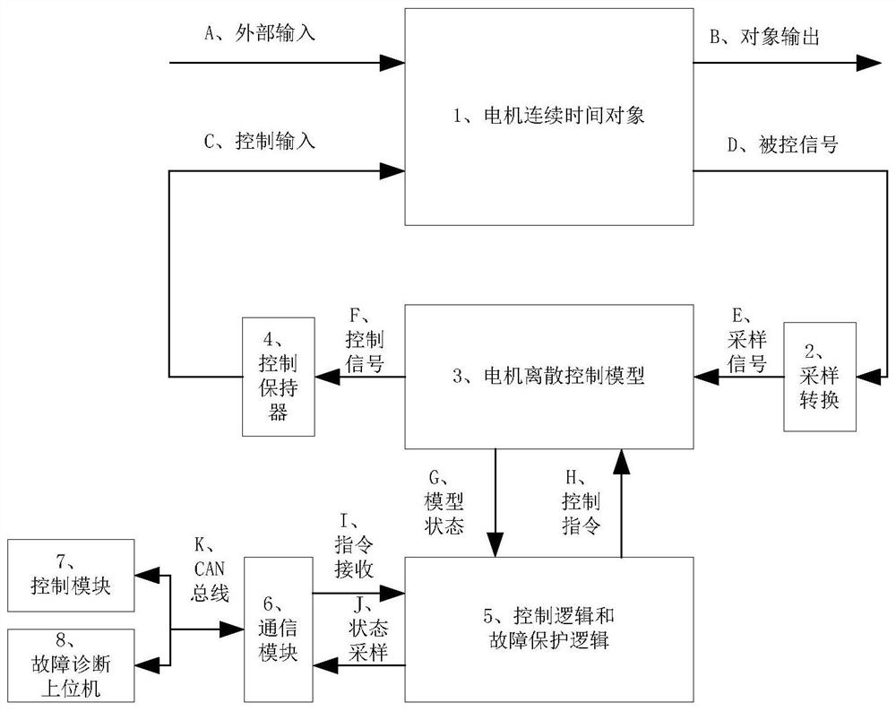
[0042]What needs to be explained in advance is that in the existing technical scheme, take the following as an example: "The control period is between 50us and 500us, if the control period is fixed at 100us, and the monitoring variables (16bit) are recorded as 20, the data generation amount DataSpeed is 3200000bps", which means that the effective information rate of the AC motor control in this example is 3.2Mbps (3200000bps), not including the efficiency loss of the communication protocol (for example, the implementation of the protocol needs to add protocol data such as head, tail, ack and interactive data , so in general, the effective information rate of a 1Mbps CAN network is around 300kbps). Therefore, it can be understood that for the amount of real-time da...


PUM


Abstract

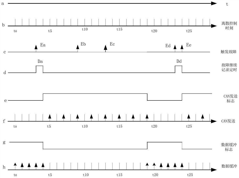
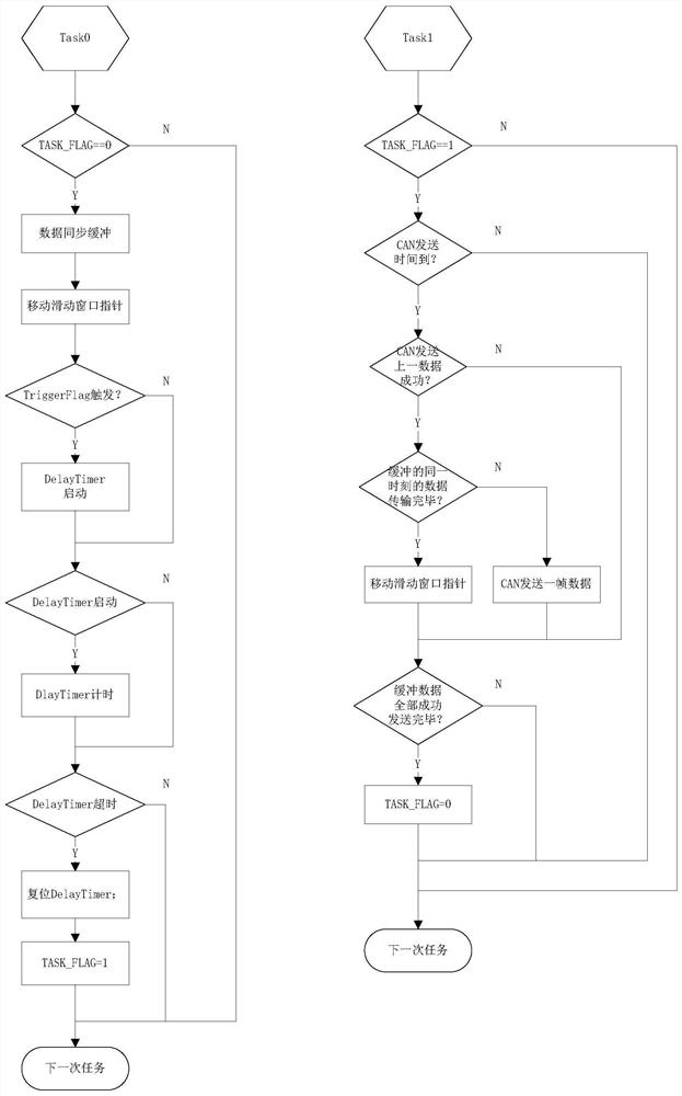
The present invention discloses a fault information collection and transmission method of a motor control system. The method comprises the steps that: according to a preset time sequence, sampling offault information, being synchronous to motor real-time control, near fault points and asynchronous transmission of fault information are achieved, wherein when sampling of the fault information nearthe fault points is performed, and a buffering area is arranged to perform data buffering of the fault information and to perform data forwarding through the buffering area when the fault informationis transmitted. In a condition without changing a current bus system, a low-speed network can be also used to effectively perform diagnosis of the fault of the real-time motor control system, and thesampling of the fault information is synchronous to the motor real-time control cycle to distinguish the successive sequence of generation of the faults so as to improve the analysis accuracy of faultpositioning.

Description

technical field [0001] The invention relates to the technical field of automatic control, in particular to a method for collecting and transmitting fault information of a motor control system. Background technique [0002] A motor is an electromagnetic device that converts or transmits electrical energy according to the law of electromagnetic induction. A motor that converts mechanical energy into electrical energy is called a generator; a motor that uses electrical energy to generate drive torque is called a motor, which is used as a power source for various electrical appliances or various machines. Traditional motor speed control methods include: series resistance speed regulation, frequency conversion speed regulation, and pole-changing speed regulation. Modern motor speed regulation is a digital control method that uses high-performance motion control chips (such as DSP) to implement vector control and direct torque control. The vector control technology was proposed ...

Claims


Application Information

Patent Timeline
Patent Type & Authority Patents(China)
IPC IPC(8): H04L12/24H04L12/40
CPCH04L12/40143H04L41/064H04L41/0677H04L2012/40215
Inventor 谭淼陈慧民谢勇波王征宇凌岳伦易慧斌梁松
Owner CHANGSHA CRRC INTELLIGENT CONTROL & NEW ENERGY TECH CO LTD
Learn More