Alternating current fan control circuit

A technology of control circuit and rectifier circuit, applied in the field of electronics, can solve the problems such as the failure of the H-bridge drive circuit, the damage to the triode, and the inability of the fan to rotate reliably and stably.

Inactive Publication Date: 2012-09-19
SHANGHAI KAKU ELECTRIC EQUIP CORP
View PDF0 Cites 6 Cited by
  • Summary
  • Abstract
  • Description
  • Claims
  • Application Information

AI Technical Summary

Problems solved by technology

Moreover, in the prior art, it is generally used to rectify the AC voltage of the power grid, and then directly pass the fan drive circuit to control the rotation of the fan. The problem that often occurs is: the DC voltage flowing into the fan drive circuit is unstable, so that the fan drive circuit Unbalanced current output, resulting in unstable rotation of the fan
In addition, the fan driving circuit in the prior art generally adopts an H-bridge driving circuit composed of four independent triodes. , but since the control signal of the H-bridge drive circuit is directly loaded on the gate of each transistor, the problem that it may cause is: when the two transistors on the same side of the H-bridge drive circuit are both turned on, the current will be Directly pass through the two triodes on the same side to form a circuit, so that the current will damage the triode, make the H bridge drive circuit useless, and the fan cannot rotate
To sum up, the AC fan control circuit in the prior art has unstable power supply and unreliable operation of the drive circuit, so that the fan cannot rotate reliably and stably.

Method used


Image

  • Alternating current fan control circuit
  • Alternating current fan control circuit
  • Alternating current fan control circuit

Examples


Embodiment Construction

[0031] The present invention is described in detail below in conjunction with accompanying drawing:

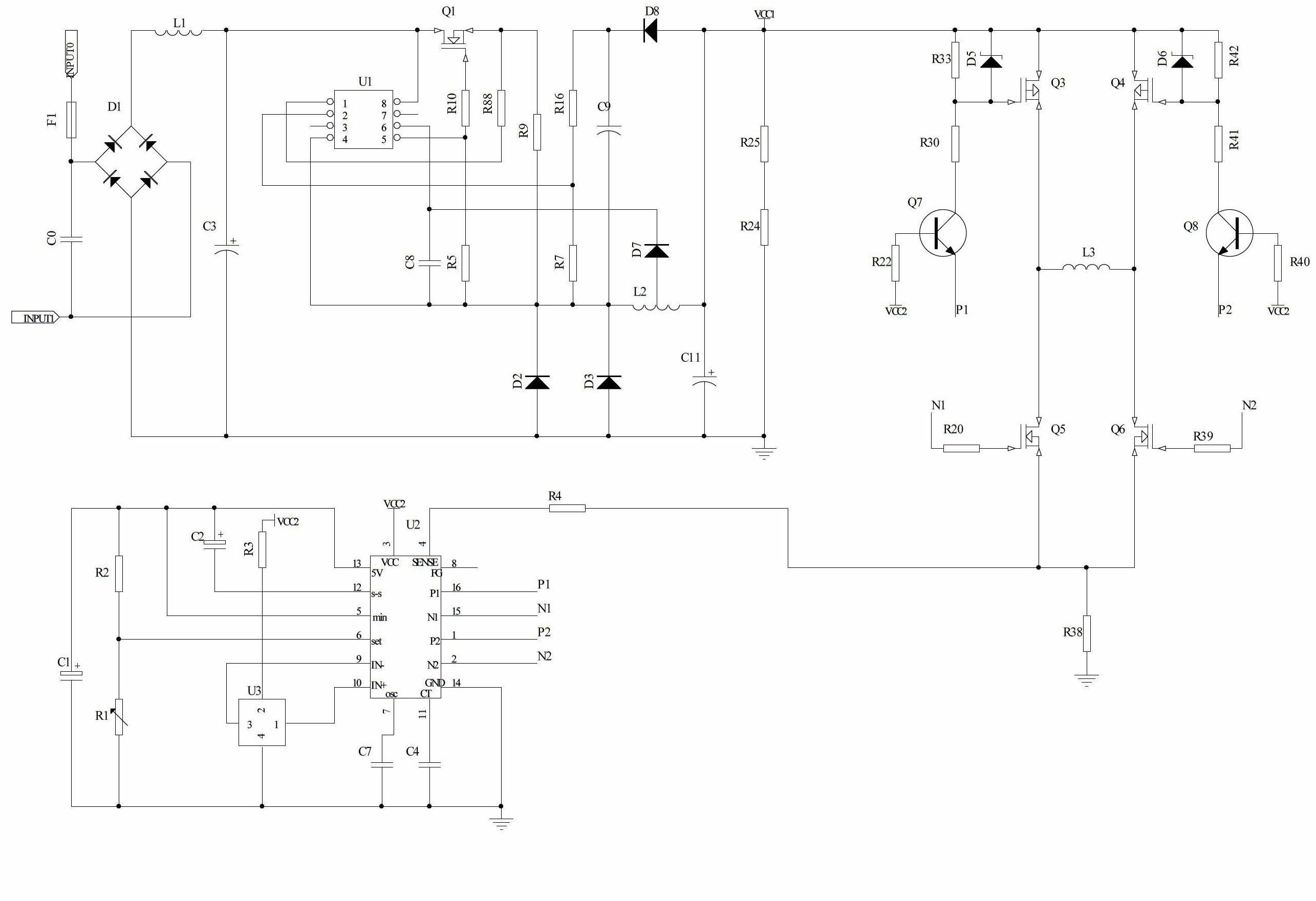
[0032] Please refer to Figures 1 to 3 , The AC fan control circuit of the embodiment of the present invention includes a rectifier circuit, a filter circuit, an electromagnetic interference circuit, a DC-DC switch circuit, a step-down circuit, and a fan drive circuit.

[0033] Please refer to figure 1 , the rectifier circuit is used to convert the AC voltage of the power grid into a DC voltage; the rectifier circuit in this embodiment is a rectifier bridge D1 composed of four diodes, and may also be a rectifier bridge block.

[0034] Please refer to figure 1 , the filter circuit is arranged at the output stage of the rectifier circuit, and is used to filter out the harmonic voltage generated by the rectifier circuit; the filter circuit in this embodiment is an LC type filter circuit, including the rectifier circuit connected in parallel The third capacitor C3 of the output s...


PUM


Abstract

The invention discloses an alternating current fan control circuit. The circuit comprises a rectification circuit, a filter circuit, an electromagnetic interference circuit, a direct current-direct current (DC-DC) switching circuit, a step-down circuit and a fan drive circuit, wherein the rectification circuit is used for converting an alternating current power supply of a power grid to a pulse direct-current power supply, the filter circuit is arranged on an output stage of the rectification circuit and used for filtering a harmonic voltage generated by the rectification circuit, the electromagnetic interference circuit is disposed on an input stage of the rectification circuit and used for preventing the alternating current fan control circuit from interfering with other circuits during operation, the DC-DC switching circuit is mounted on an output stage of the filter circuit and used for converting the pulse direct-current power supply output by the rectification circuit and the filter circuit to a first direct current power supply, the step-down circuit is used for performing a voltage stabilization to the first direct current power supply output by the DC-DC switching circuit and outputting a second direct current power supply, and the fan drive circuit is used for driving a fan to forwardly rotate or reversely rotate. The alternating current fan control circuit is stable and reliable during operating.

Description

technical field [0001] The invention relates to the field of electronic technology, in particular to an AC fan control circuit. Background technique [0002] AC fans are mainly used for heat dissipation of electronic products. Widely used in digital electronics, home appliances, machinery, manufacturing equipment and other fields. The AC fan is correspondingly provided with a fan drive circuit for driving the fan of the fan to rotate to dissipate heat from the electronic product. Because the driving circuit of the AC fan first converts the AC voltage of the power grid into a DC voltage, and then drives the fan. Moreover, in the prior art, it is generally used to rectify the AC voltage of the power grid, and then directly pass the fan drive circuit to control the rotation of the fan. The problem that often occurs is: the DC voltage flowing into the fan drive circuit is unstable, so that the fan drive circuit The current output of the fan is unbalanced, resulting in unstabl...

Claims


Application Information

Patent Timeline
Patent Type & Authority Applications(China)
IPC IPC(8): F04D27/00
Inventor 郭建议
Owner SHANGHAI KAKU ELECTRIC EQUIP CORP
Why Eureka
Try Eureka