Direct-acting overflow valve, direct-acting overflow valve group and hydraulic overflow loop

A direct-acting relief valve and hydraulic oil technology, applied in servo motor components, fluid pressure actuators, mechanical equipment, etc., can solve the problems of system heat generation, lagging response speed, high processing cost, etc., and achieve overall easy operation, Achieve unloading function and low processing cost

Active Publication Date: 2012-09-19
CHANGDE ZHONGLIAN ZHONGKE HYDRAULIC
View PDF13 Cites 21 Cited by
  • Summary
  • Abstract
  • Description
  • Claims
  • Application Information

AI Technical Summary

Problems solved by technology

This will cause the action speed of the actuator to slow down, the system will heat up, and the efficiency will decrease
At the same time, it is known that the structure of the pilot relief valve is relatively complicated, the processing cost is high, and there will be a certain hysteresis in the response speed
[0005] Chinese utility model patent application CN2086355U discloses a differential pressure direct-acting overflow valve, figure 2 Shown is the differential pressure direct-acting relief valve disclosed in this utility model patent application. It should be pointed out here that the differential pressure direct-acting relief valve not only has no remote control port and no unloading function, but also has Analysis on even its basic overflow functionality is not possible, see figure 2 As shown, the differential pressure direct-acting relief valve forms a valve internal pressure chamber together with the valve core 10 through the pressure balance valve sleeve 13, and through the throttle hole formed on the valve core 10, the internal pressure chamber and the relief valve The input port 19 communicates with the input port 19, and there is no mention of the hydraulic oil action area on the upper end surface of the valve core 10 in the valve internal pressure chamber and the hydraulic oil of the input port 19 acting on the valve core 10. There is an area difference in the hydraulic oil action area of ​​the conical surface at the lower end, from figure 2 From the specific structure shown, it can only be considered that the hydraulic oil action area of ​​the upper end surface of the spool 10 is equal to the hydraulic oil action area of ​​the lower tapered surface of the spool 10. In this case, due to the incompressibility of the hydraulic oil , when the oil pressure of the hydraulic oil at the input port 19 increases instantaneously, the spool 10 has a tendency to move upward, the hydraulic oil in the pressure chamber in the valve is instantly compressed, and the oil pressure of the hydraulic oil therein also rises instantaneously Since the hydraulic oil action area of ​​the upper end surface of the spool 10 is equal to the hydraulic oil action area of ​​the lower conical surface of the spool 10, the oil pressure of the hydraulic oil in the pressure chamber in the valve only needs to rise to the same level as the input port 19. The oil pressure at the position is equal, and the thrust on the lower end surface of the spool 10 can be balanced. In this case, since the oil pressure in the pressure chamber in the valve is equal to the oil pressure at the input port 10, the pressure in the pressure chamber in the valve The hydraulic oil will not return to the input port 19 through the orifice on the spool 10
Therefore, only judging from the technical content disclosed in the utility model patent application CN2086355U, the differential pressure direct-acting relief valve is actually rigid as a whole, and it cannot realize the differential pressure relief function, let alone the remote control port. Realize unloading function

Method used


Image

  • Direct-acting overflow valve, direct-acting overflow valve group and hydraulic overflow loop
  • Direct-acting overflow valve, direct-acting overflow valve group and hydraulic overflow loop
  • Direct-acting overflow valve, direct-acting overflow valve group and hydraulic overflow loop

Examples


Embodiment Construction

[0049] The specific embodiments of the present invention will be described in detail below in conjunction with the accompanying drawings. It should be understood that the specific embodiments described here are only used to illustrate and explain the present invention, and the protection scope of the present invention is not limited to the following specific embodiments. .

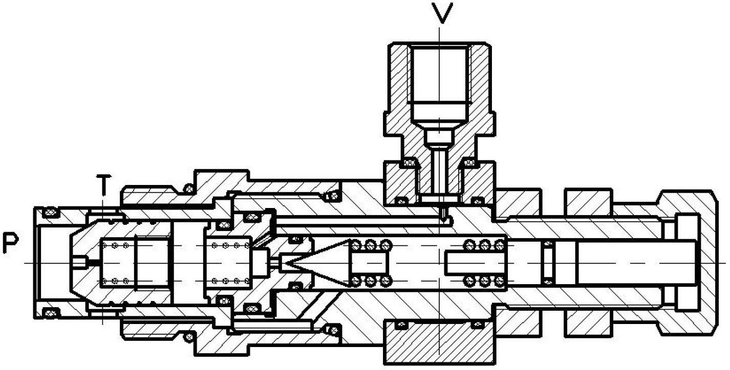
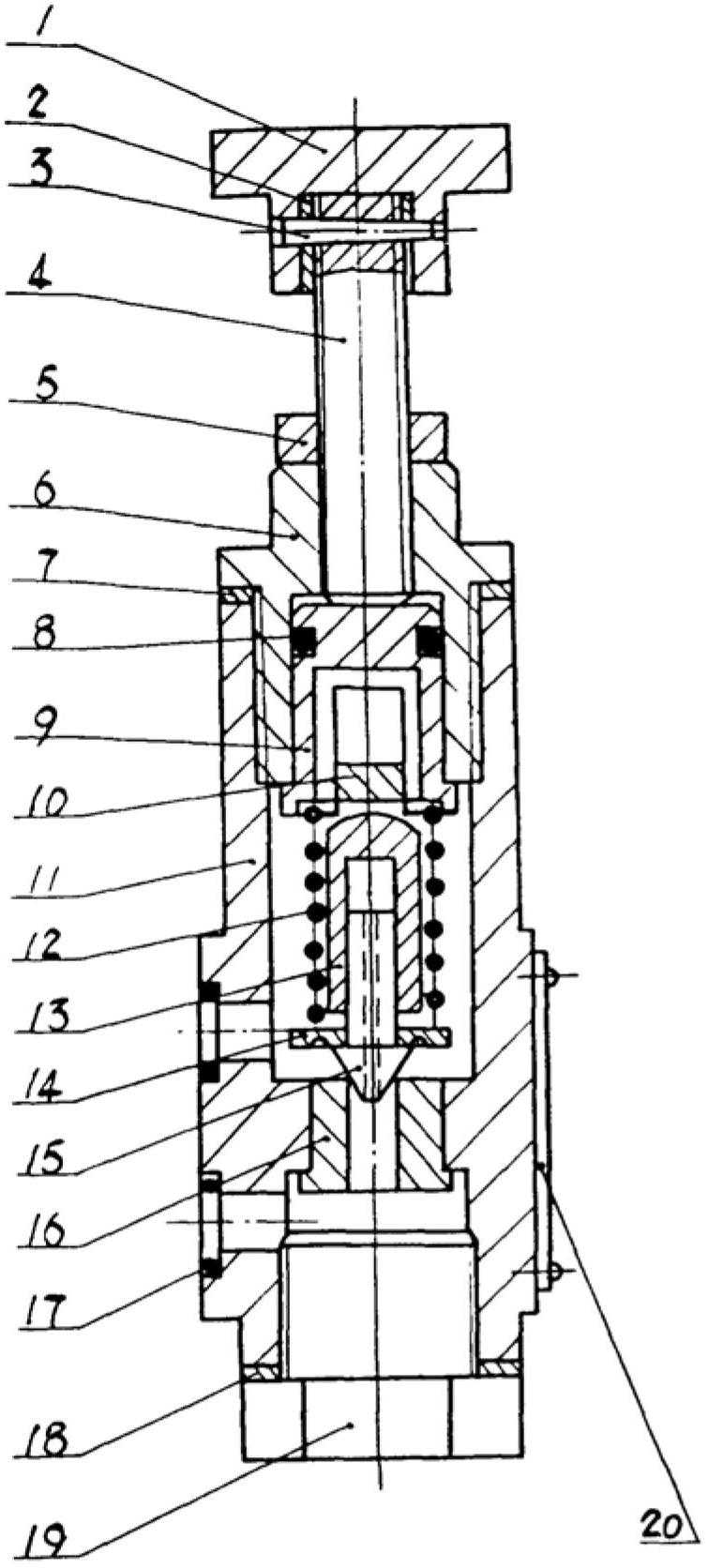
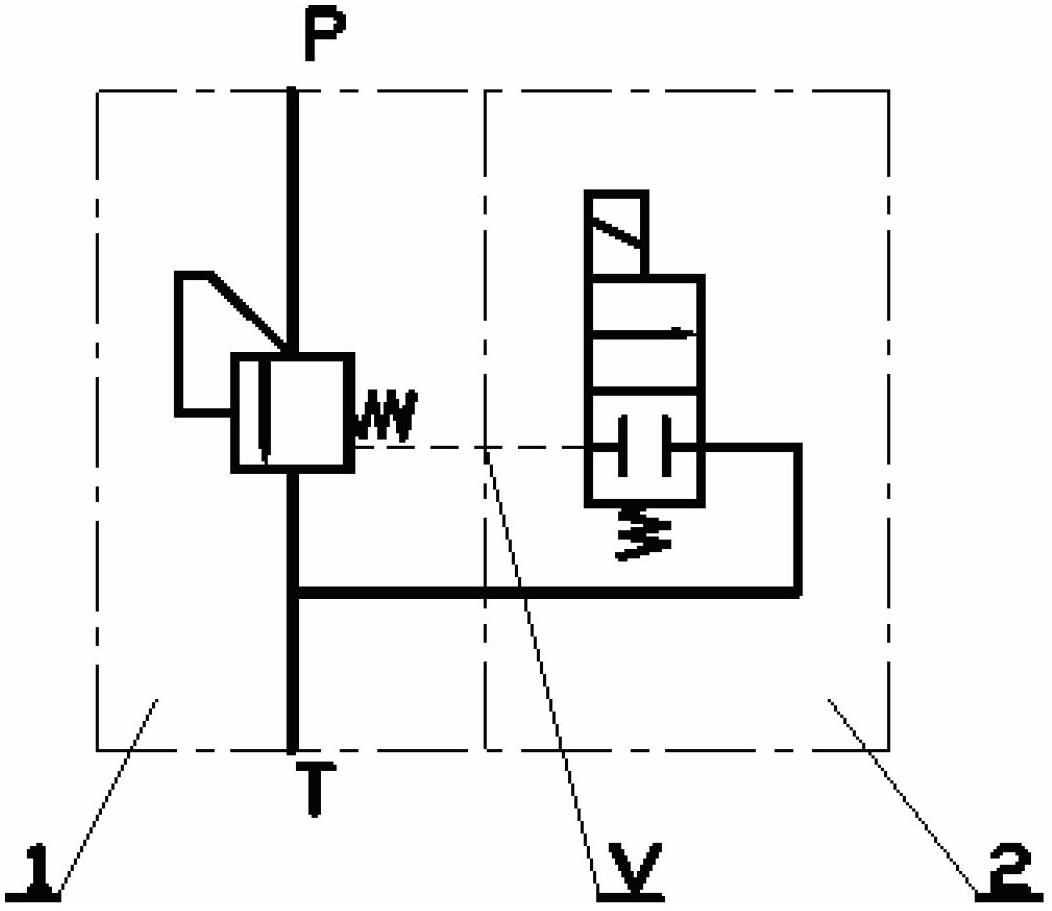
[0050] Figure 3 to Figure 6 It shows a specific implementation of the direct-acting overflow valve of the present invention, the formula that needs to be explained, Figure 3 to Figure 6 What is shown is only the preferred structure of the direct-acting overflow valve of the present invention, and the technical concept of the direct-acting overflow valve of the present invention is not limited to the specific details shown in the figure. In addition, in the following descriptions, unless the communication relationship is specifically stated, the corresponding chambers should be kept sealed or substantial...


PUM


Abstract

The invention discloses a direct-acting overflow valve, comprising a remote control opening (V) and a hydraulic oil counteractive cavity (X) communicated with the remote control opening (V), wherein the hydraulic oil counteractive cavity (X) is communicated with an oil inlet (P); the hydraulic oil in the hydraulic oil counteractive cavity (X) acts on a valve core (102) in the same direction as the spring acts on a valve core (10); the hydraulic oil on an oil inlet pressure surface has an effective area more than the hydraulic oil on the pressure surface of the valve core (102) exposed in the hydraulic oil counteractive cavity (X). Additionally, the invention also provides a direct-acting overflow valve group comprising the direct-acting overflow valve, and a hydraulic overflow loop. As the remote control opening is added in the direct-acting overflow valve, the direct-acting overflow valve has an unloading function. Meanwhile, with the adoption of the direct-acting overflow valve, the functions of overflowing with low flow and unloading with high flow are realized when the overflowing and unloading functions are realized due to the more optimized structural design.

Description

technical field [0001] The invention relates to an overflow valve, in particular to a direct-acting overflow valve. In addition, the present invention also relates to a direct-acting overflow valve group and a hydraulic overflow circuit comprising the direct-acting overflow valve. Background technique [0002] The relief valve is a commonly used hydraulic control valve in the hydraulic system. It can be used to control the maximum pressure of the hydraulic system on the main oil circuit of the hydraulic system, and can also be used on the working oil circuit of a hydraulic actuator (such as a hydraulic cylinder) to control The operating pressure of the actuator. Relief valves are mainly divided into direct-acting relief valves and pilot-operated relief valves. Direct-acting relief valves have the advantages of simple structure, low processing cost, and sensitive action. However, the existing direct-acting relief valves There are certain limitations in application due to it...

Claims


Application Information

Patent Timeline
Patent Type & Authority Applications(China)
IPC IPC(8): F15B13/02
Inventor 陈志超潘文华曾浩徐尧
Owner CHANGDE ZHONGLIAN ZHONGKE HYDRAULIC
Why Eureka
Try Eureka