Hydraulic oil tank pneumatic pressurization system of engineering machine

A technology of hydraulic oil tank and pneumatic booster, which is used in fluid pressure actuation system testing, fluid pressure actuation system safety, mechanical equipment, etc. It can solve the problems of pump air suction, aggravated vibration, noise, and poor pump self-priming ability. , to achieve the effect of increasing the pressure of the oil suction port, prolonging the replacement cycle, and low energy consumption

Active Publication Date: 2020-02-11
XUZHOU XCMG MINING MACHINERY CO LTD
View PDF6 Cites 0 Cited by
  • Summary
  • Abstract
  • Description
  • Claims
  • Application Information

AI Technical Summary

Problems solved by technology

Large-scale construction machinery includes a hydraulic system. The hydraulic pump in the system has a large displacement, and the self-priming ability of the pump is relatively poor. In addition, the atmospheric pressure on the plateau is low, and the pump is prone to cavitation.
Studies have shown that 80% of hydraulic system failures are caused by system pollution, and 16% are caused by air suction, which will cause cavitation in the hydraulic system, aggravate vibration and noise, and seriously affect the service life of equipment. In order to make the existing large construction machinery To meet the requirements of use in plateau areas, it is necessary to increase the suction pressure of the pump

Method used


Image

  • Hydraulic oil tank pneumatic pressurization system of engineering machine
  • Hydraulic oil tank pneumatic pressurization system of engineering machine
  • Hydraulic oil tank pneumatic pressurization system of engineering machine

Examples


Embodiment Construction

[0025] In order to make the objectives, technical solutions and advantages of the present invention clearer, the technical solutions in the embodiments of the present invention will be described in more detail below in conjunction with the drawings in the embodiments of the present invention. In the drawings, the same or similar reference numerals denote the same or similar components or components having the same or similar functions throughout. The described embodiments are some, but not all, embodiments of the invention. The embodiments described below by referring to the figures are exemplary and are intended to explain the present invention and should not be construed as limiting the present invention. Embodiments of the present invention will be described in detail below in conjunction with the accompanying drawings.

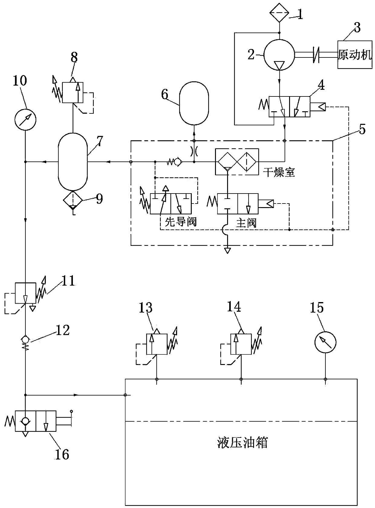
[0026] Such as figure 1 As shown, a hydraulic oil tank pneumatic pressurization system for construction machinery mainly includes a suction filter 1, an...


PUM


Abstract

The invention discloses a hydraulic oil tank pneumatic pressurization system of an engineering machine. The system comprises an air compressor, a reversing valve, a dryer, a regeneration air storage tank, an air storage tank, a pressure reducing valve, a hydraulic oil tank and an overflow valve. The air compressor is connected with a prime mover and driven by the prime mover. The reversing valve is connected between an outlet of the air compressor and an inlet of the dryer, the regeneration air storage tank and the air storage tank are connected with an outlet of the dryer, the pressure reducing valve is connected between the air storage tank and the hydraulic oil tank, and the overflow valve is mounted on the hydraulic oil tank. The pascal's principle is used, compressed air is input intothe hydraulic oil tank, the absolute barometric pressure in the oil tank can be improved, the pressure of an oil sucking port of a hydraulic pump can be improved, the suction empty phenomenon is avoided, and normal use of the engineering machine in the plateau section is ensured.

Description

technical field [0001] The invention relates to a pneumatic pressurization system for hydraulic oil tanks of engineering machinery, which belongs to the field of mechanical equipment. Background technique [0002] Large-scale construction machinery is the main construction machinery in the construction of earthwork in mines. With the development of my country's economy, the demand for resources continues to increase, and it is necessary to vigorously develop the development of mining resources in plateau areas. Large-scale construction machinery includes a hydraulic system. The hydraulic pump in the system has a large displacement and relatively poor self-priming ability. In addition, the atmospheric pressure on the plateau is low, and the pump is prone to cavitation. Studies have shown that 80% of hydraulic system failures are caused by system pollution, and 16% are caused by air suction, which will cause cavitation in the hydraulic system, aggravate vibration and noise, an...

Claims


Application Information

Patent Timeline
Patent Type & Authority Applications(China)
IPC IPC(8): F15B3/00F15B1/26F15B13/02F15B19/00F15B20/00
CPCF15B1/26F15B3/00F15B13/02F15B19/00F15B20/00
Inventor 李寿鹏史继江秦家升石立京孙文庆吕建森
Owner XUZHOU XCMG MINING MACHINERY CO LTD
Why Eureka
Try Eureka