Non-contact engine thrust testing method and device

A non-contact, test method technology, applied in the direction of engine testing, measuring device, machine/structural component testing, etc., can solve the problems of inability to guarantee the aerodynamic parameters of data points, long working cycle of engine thrust, etc.

Inactive Publication Date: 2012-09-19
NORTHWESTERN POLYTECHNICAL UNIV
View PDF7 Cites 33 Cited by
  • Summary
  • Abstract
  • Description
  • Claims
  • Application Information

AI Technical Summary

Problems solved by technology

In principle, this type of method can indeed obtain the actual thrust generated by the engine when it is working, but this method cannot guarantee that the data points collected at different positions are the corresponding aerodynamic parameters at the same time in the measurement of impact force and periodic thrust. , so the measurement method of aerodynamic thrust is only suitable for traditional aero-engines, that is, when the tail exhaust airflow is stable
Moreover, in order to measure the aerodynamic parameters of the engine tail airflow, installing a measuring probe at the exhaust section of the tail will inevitably have a certain impact on the working conditions of the engine itself
And the acquisition of the final thrust requires ring integration of the measurement results of the entire engine tail section. In order to ensure the accuracy of the measurement, the measurement sampling points need to be arranged as densely as possible, so the working cycle of this method to measure the engine thrust will be relatively long. long

Method used


Image

  • Non-contact engine thrust testing method and device
  • Non-contact engine thrust testing method and device
  • Non-contact engine thrust testing method and device

Examples


Embodiment Construction

[0045] Describe the present invention below in conjunction with specific embodiment:

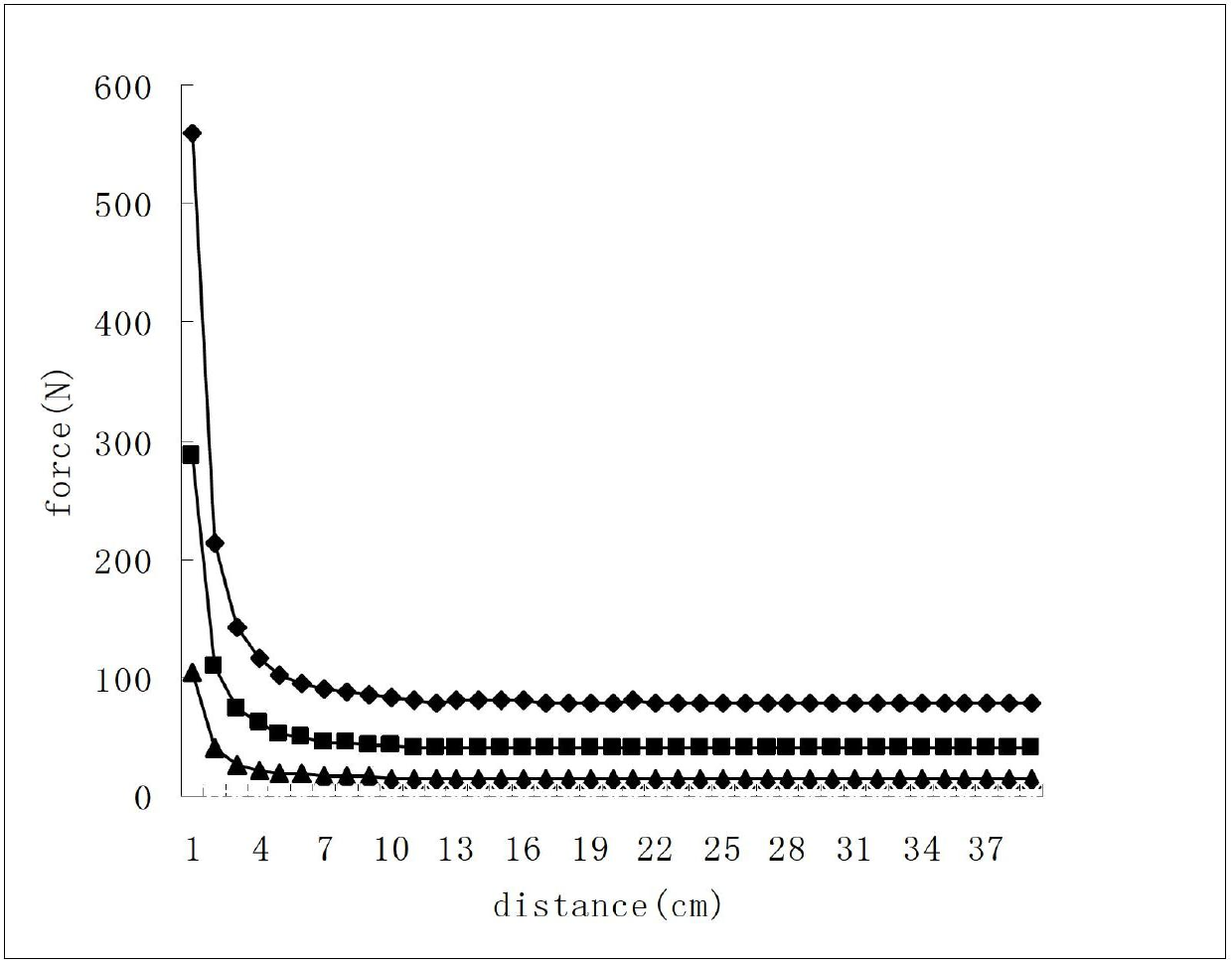
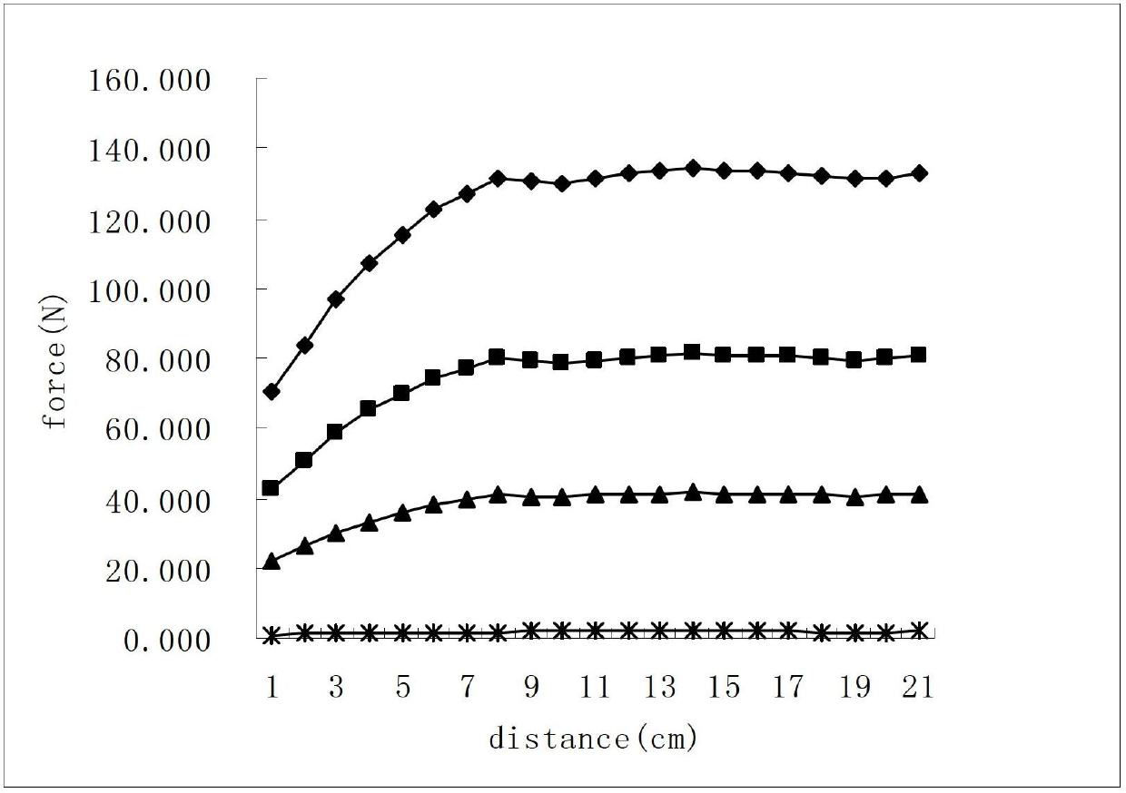
[0046] In this embodiment, a single-tube pulse detonation engine is taken as an example, and thrust measurement is performed on a pulse detonation engine with a working frequency of 25 Hz.

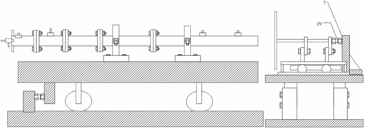
[0047] Measuring devices such as image 3 As shown, the single-tube pulse detonation engine is fixed on the platform, and the overall thrust test device is placed at the tail of the engine. The thrust testing device includes a supporting platform and a measuring assembly.

[0048] Refer to attached Figure 4 And attached Figure 5 , The support platform is divided into an upper sub-frame 1 and a lower sub-frame 2, the upper sub-frame and the lower sub-frame are nested together and connected by bolt positioning. By changing the installation positioning holes of the bolts, the installation height of the upper sub-frame and the lower sub-frame can be adjusted.

[0049] In this embodiment, the overall h...


PUM

PropertyMeasurementUnit
radiusaaaaaaaaaa

Abstract

The invention provides a non-contact engine thrust testing method and a non-contact engine thrust testing device. The method comprises the following steps of performing analog calculation by using computational fluid dynamic (CFD) software to acquire the radius of a smooth supporting panel which can accord with the condition that an engine can work normally and determine the critical mounting distance; and determining the mounting position of the testing device according to an analog calculation result, obtaining a relation between thrust and the distance by a plurality of times of non-contact measurement, performing first-order linear fitting and obtaining the thrust value at a position in which the mounting distance is 0 by using a linear fitting equation, wherein the thrust value is a pneumatic thrust value generated by the engine. The method and the device do not have an obvious requirement on the structure of the engine; the engine body is not required to be mounted on a moving frame; a phenomenon that the panel cannot be smoothly mounted is avoided; and the actual thrust generated by the engine can be obtained by performing thrust measurement a plurality of points.

Description

technical field [0001] The invention relates to the technical field of engine testing, in particular to a non-contact engine thrust testing method and device. It is mainly used for thrust measurement of aero-engines, etc. Background technique [0002] At present, traditional aeroengine thrust measurement devices can be roughly divided into two categories according to different applications. [0003] One type is mainly used for engine test run in the factory. The principle is to install the aero-engine on the moving frame, and then fix the whole moving frame to the top of the test room through several steel ropes of equal length, at the same position as the moving frame. Install the static frame, and install the pressure sensor at the only contact force point between the moving frame and the static frame. The principle of thrust measurement is mainly that when the engine is working, the thrust generated will push the moving frame to the direction of the stationary frame. Wh...

Claims


Application Information

Patent Timeline
Patent Type & Authority Applications(China)
IPC IPC(8): G01M15/00G01L5/00
Inventor 郑龙席李超黄希桥李勍
Owner NORTHWESTERN POLYTECHNICAL UNIV
Why Eureka
Try Eureka