Pressurizing constant temperature control device and core test system

A technology of constant temperature control and equipment, applied in the field of control equipment and core flooding experiments, can solve the problems of constant temperature control of the core flooding experimental system that cannot be scanned by CT, and achieve the effect of solving difficult construction and high cost.

Active Publication Date: 2012-09-19
PETROCHINA CO LTD
View PDF7 Cites 13 Cited by
  • Summary
  • Abstract
  • Description
  • Claims
  • Application Information

AI Technical Summary

Problems solved by technology

[0004] The embodiment of the present invention provides a pressurized and constant temperature control device and a core testing system, using two circulation pumps with opposite running directions as a dua...

Method used


Image

  • Pressurizing constant temperature control device and core test system
  • Pressurizing constant temperature control device and core test system
  • Pressurizing constant temperature control device and core test system

Examples


Embodiment Construction

[0028] The following will clearly and completely describe the technical solutions in the embodiments of the present invention with reference to the accompanying drawings in the embodiments of the present invention. Obviously, the described embodiments are only some, not all, embodiments of the present invention. Based on the embodiments of the present invention, all other embodiments obtained by persons of ordinary skill in the art without making creative efforts belong to the protection scope of the present invention.

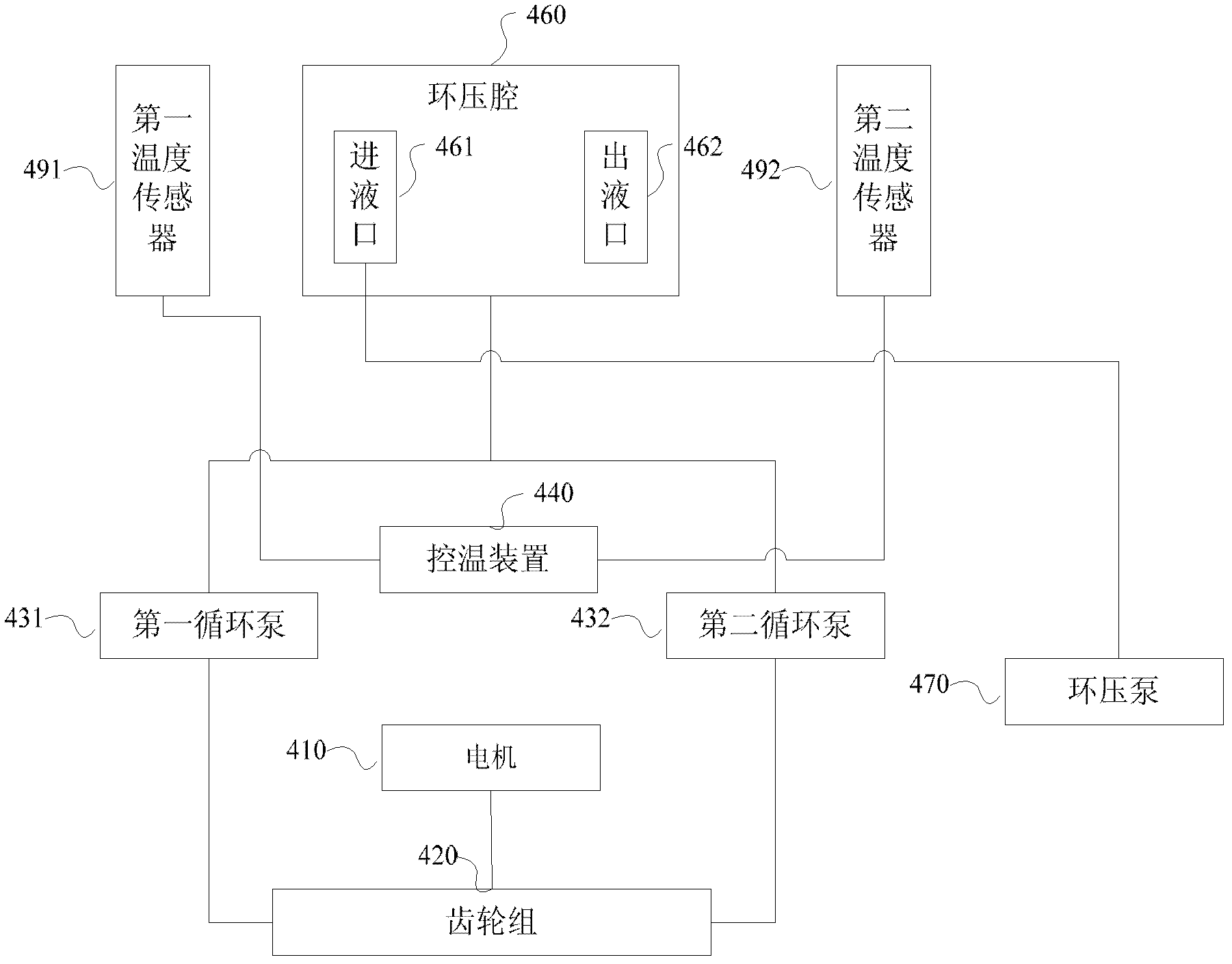
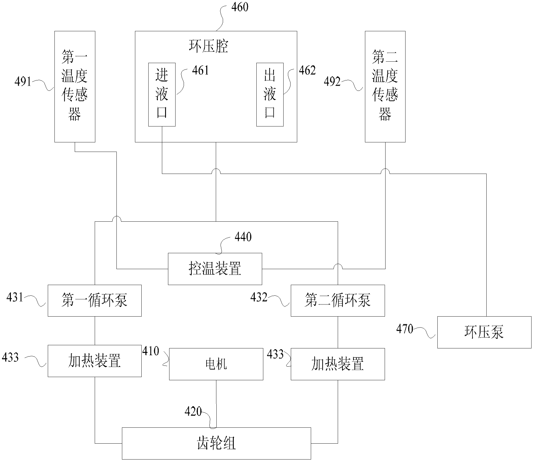
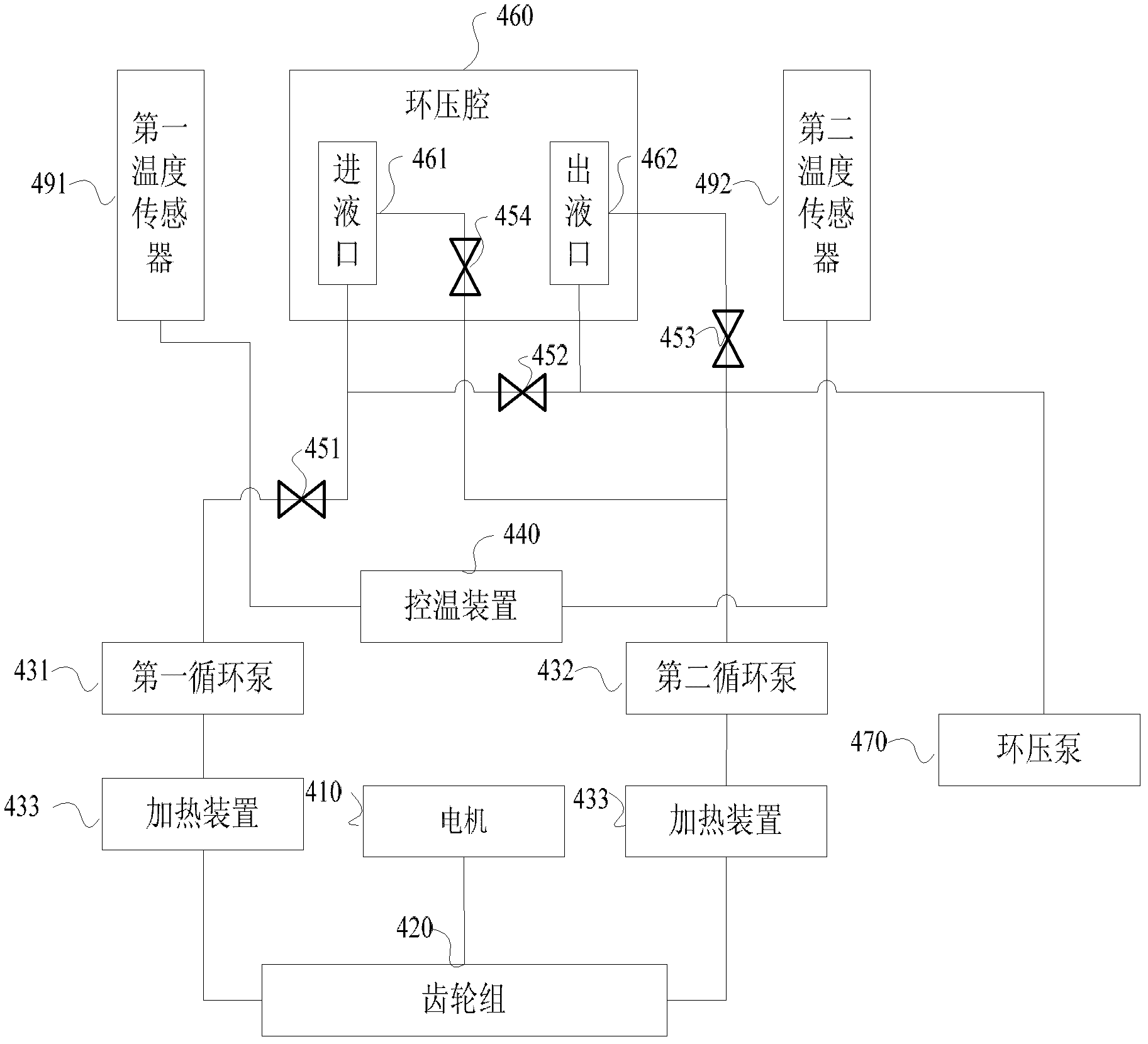
[0029] figure 1 It is a schematic structural diagram of Embodiment 1 of a pressure constant temperature control device provided in an embodiment of the present invention, which is represented by figure 1 It can be seen that the pressurized constant temperature control equipment includes:

[0030] A motor 410, a gear set 420 connected to the motor 410, a first circulation pump 431 and a second circulation pump 432 respectively connected to the gear set 420;

...


PUM


Abstract

The embodiment of the invention provides a pressurizing constant temperature control device and a core test system. The core test system comprises a CT (computerized tomography) scanner (1), a core holder (2), an injection pump (3), and the pressurizing constant temperature control device (4). The pressurizing constant temperature control device (4) comprises a motor (410), a gear set (420), a first circulating pump (431), a second circulating pump (432), a first temperature sensor (491), a second temperature sensor (492), a temperature control device (440), one-way valves (451-454), and an annular pressure pump (470). The two circulating pumps with opposite operational directions are used as a double power device, so that the problem that baking ovens and like products cannot be used to perform constant temperature control to core flooding experiments using the CT scanner in the prior art is solved.

Description

technical field [0001] The present invention relates to a rock core displacement experiment, in particular to a control device in the rock core displacement experiment, specifically a pressure constant temperature control device and a rock core testing system. Background technique [0002] In the process of oil development, it is often necessary to carry out indoor core displacement experiments to evaluate the oil displacement effect and fluid properties. In the early 1980s, Vinegar and others introduced CT scanning technology into the petroleum industry for the first time to carry out research on reservoir physics and other aspects. After that, CT technology has developed rapidly and has been widely used as a routine testing technology in core analysis. In core description, core heterogeneity determination, determination of core sample processing procedures, quantitative analysis of fractures, online saturation measurement, flow experiment research, etc. Using CT scanning ...

Claims


Application Information

Patent Timeline
IPC IPC(8): G01N15/08G01N23/083
Inventor 吕伟峰张祖波刘庆杰马德胜吴康云严守国罗蔓莉
Owner PETROCHINA CO LTD
Why Eureka
Try Eureka