
Armored sensing optical cable

A fiber optic cable and armoring technology, applied in measuring devices, measuring heat, instruments, etc., can solve the problems of large outer diameter, complex structure, large fiber loss, etc., and achieve soft bending performance, accurate temperature measurement accuracy, and good compression resistance Effect

Inactive Publication Date: 2012-09-19
东捷光电科技(苏州)有限公司
View PDF4 Cites 7 Cited by
  • Summary
  • Abstract
  • Description
  • Claims
  • Application Information

AI Technical Summary

Problems solved by technology

When the ordinary optical cable is used in these outdoor environments, if it is squeezed, pulled and other external forces, the loss of the fiber may be too large, which will affect the accuracy of the sensing system, or even break the fiber.
Therefore, ordinary indoor optical cables are not suitable as sensing optical cables for outdoor sensing in subways, tunnels, dams, bridges, etc.
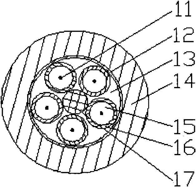
While ordinary outdoor optical cables (such as figure 2 ), its structure is complex, the outer diameter is larger, the weight is heavier, and the construction and laying is very inconvenient
The most important thing is that due to the structural characteristics of the outdoor optical cable, the outer layer of the optical fiber has a complex structure, which causes the optical fiber to respond slowly to the temperature of the outside world, and there may even be a large difference between the temperature measurement result of the optical fiber and the actual temperature, which affects the test effect.
Therefore, although ordinary outdoor optical cables have good tensile and compressive properties, their structural characteristics make them unable to meet the temperature measurement accuracy requirements.

Method used


Image

  • Armored sensing optical cable
  • Armored sensing optical cable
  • Armored sensing optical cable

Examples


Embodiment Construction

[0025] The present invention is described below in conjunction with accompanying drawing.

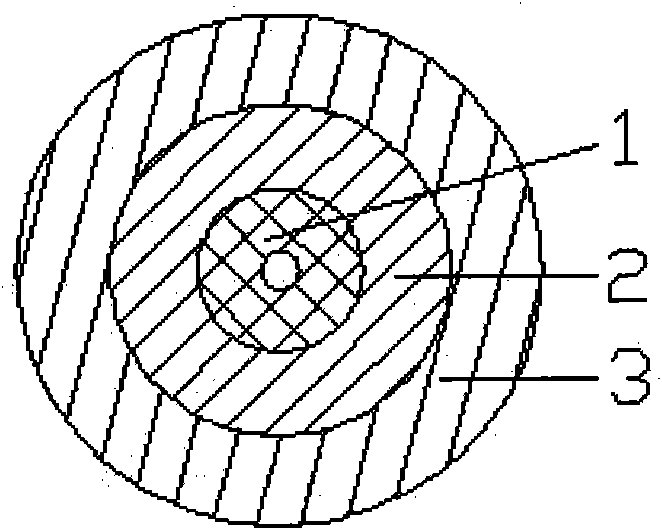
[0026] as attached figure 1 The common sensing optical cable of the prior art shown includes a tight-wrapped optical cable 1, an optical cable tensile element 2, and a sheath layer 3; the optical cable tensile element 2 wraps the tight-wrapped optical cable 1; the sheath layer 3 wraps Optical cable tensile element 2.

[0027] as attached figure 2 The common outdoor sensing optical cable of the prior art shown includes an optical fiber 11, a plastic-coated aluminum tape 12, a cable core filler 13, a polyethylene sheath 14, a sleeve filler 15, a loose tube 16, and a central strengthening core 17 .

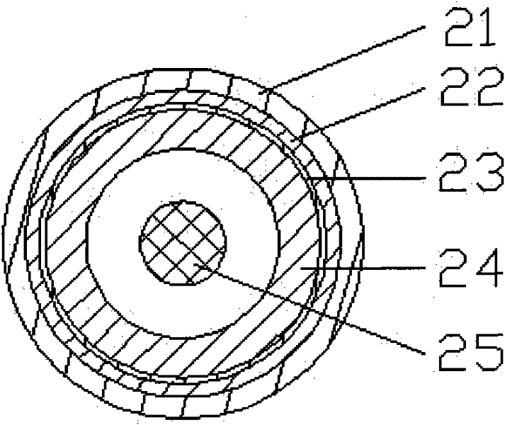
[0028] as attached image 3 The first embodiment of a kind of armored sensing optical cable of the present invention shown, sheath 21, metal braid 22, Kevlar (Kevlar) 23, metal hose 24, tight package optical fiber 25; The metal hose 24 wraps the tightly wrapped optical fiber 25; the Kevl...


PUM


Abstract

The invention discloses an armored sensing optical cable, which comprises a tightly packaged fiber, a metal hose, a metal mesh grid and an outer jacket layer, wherein the tightly packaged fiber is wrapped by the metal hose; the metal mesh grid is coated out of the tightly packaged fiber; the outer jacket layer is coated on the metal mesh grid; when one tightly packaged fiber is provided, a laeyr of Kevlar is arranged between the metal hose and the metal mesh grid; when multiple tightly packaged fibers are provided, a layer of Kevlar and a flameproof inner jacket are arranged between the metal hose and the tightly packaged fiber in sequence. The armored sensing optical cable is armored by the small metal hose, the minimum outer diameter is only 0.9 mm after armored, and the minimum outer diameter of the optical cable is only 1.8 mm after the optical cable is formed. The interval between the tightly packaged fiber of the armored sensing optical cable and the external environment is small, the temperature measuring speed of the armored optical cable is quicker than that of the common optical cable, and the temperature measuring precision is accurate. The problems of complicated structure of a common outdoor optical cable structure, isolation of the optical fiber and the external environment and poor temperature measuring effect are solved.

Description

technical field [0001] The invention relates to an optical fiber temperature measurement system element, in particular to an armored sensing optical cable for temperature sensing with optical fiber as the main body, belonging to the technical field of optical elements, systems or instruments. Background technique [0002] Optical fiber sensing technology is a product of modern communication and a brand-new technology gradually developed with the development of optical fiber and communication technology. During the transmission of light, it is affected by the external environment, such as temperature, pressure, etc., resulting in changes in the intensity, phase, frequency, polarization state and other light waves of the transmitted light. The corresponding physical quantities can be obtained by monitoring changes in these quantities. [0003] Compared with various traditional electrical sensors, fiber optic sensors have a series of advantages: high sensitivity, corrosion res...

Claims


Application Information

Patent Timeline
IPC IPC(8): G02B6/44G01K11/32
Inventor 吕政鸿
Owner 东捷光电科技(苏州)有限公司
Learn More