
Leakage protection device with extended function

A technology of leakage protection device and extended function, which is applied in the field of leakage protection device and leakage protection device with extended function, which can solve the problem of single function and achieve the effect of circuit temperature protection

Inactive Publication Date: 2014-06-04
常熟市立得电器有限公司
View PDF6 Cites 9 Cited by
  • Summary
  • Abstract
  • Description
  • Claims
  • Application Information

AI Technical Summary

Problems solved by technology

Most of the existing leakage protection devices use residual current detection technology, which only detects and provides protection for electrical leakage, and the function is relatively single
It cannot provide safety protection for potential safety hazards such as abnormal electrification of the ground wire, lack of ground wire, and excessive temperature rise caused by poor contact between the plug and the socket.

Method used


Image

  • Leakage protection device with extended function
  • Leakage protection device with extended function

Examples


Embodiment 1

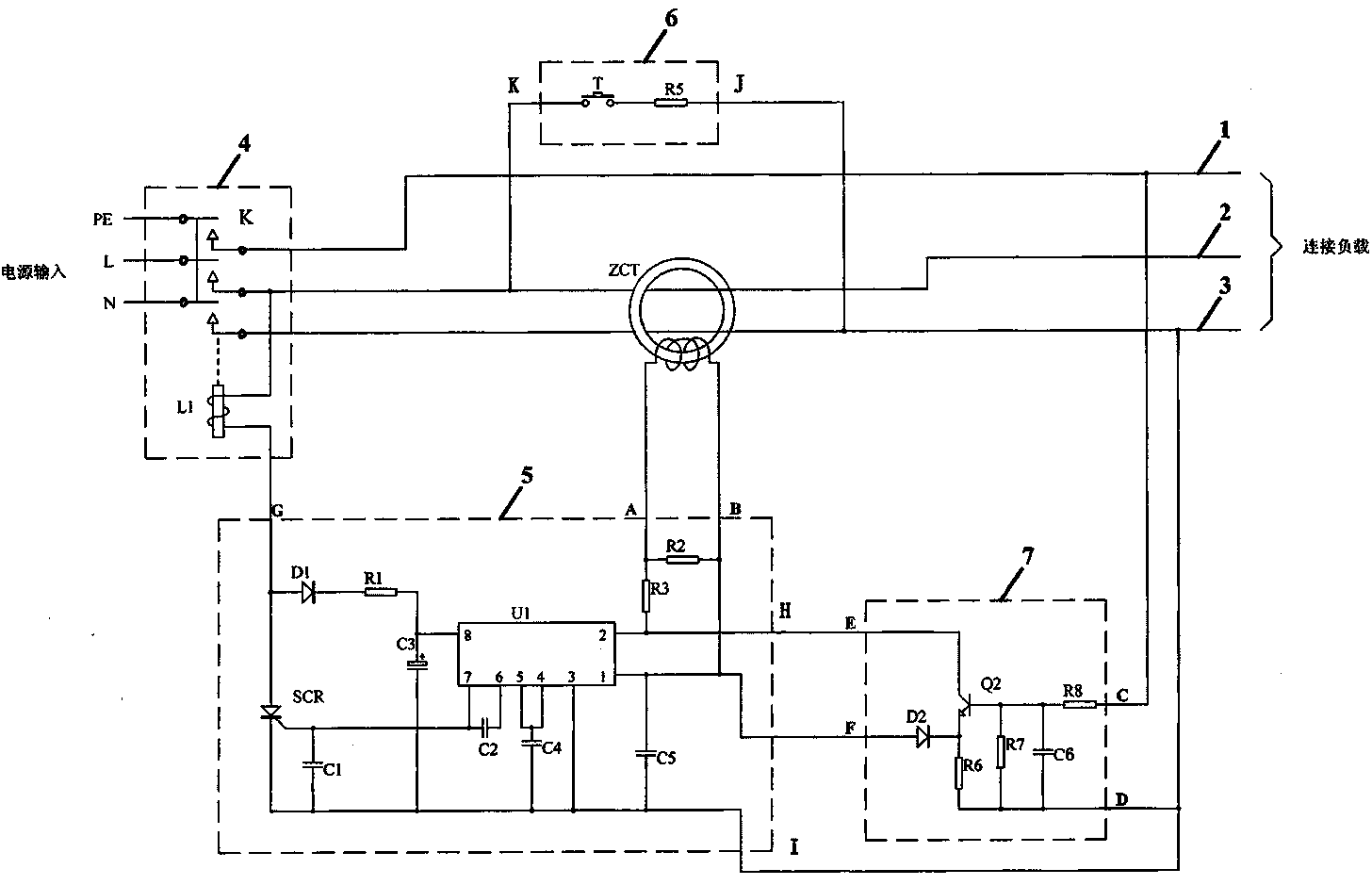
[0013] see figure 1 , a leakage protection device with extended functions, including zero-sequence current transformer ZCT, release 4, IC drive circuit 5, test circuit 6 and function expansion circuit 7. Among them, the release 4 is composed of an electromagnet coil L1 and a switch K with three sets of contacts; the IC drive circuit 5 includes a diode D1, resistors R1~R3, capacitors C1~C5, a silicon controlled rectifier SCR and an integrated chip U1 , in the present invention, the integrated chip U1 adopts M54123; the test circuit 6 includes a button switch T and a resistor R5; the function expansion circuit 7 includes a diode D2, resistors R6-R8, a capacitor C6 and a transistor Q2, wherein the diode D2 can also be replaced by a resistor , the transistor Q2 is a single transistor, but it can also be a composite transistor. Specifically, one end of the three groups of contacts of the switch K of the release 4 is respectively connected to the N terminal (neutral line), the L te...

Embodiment 2

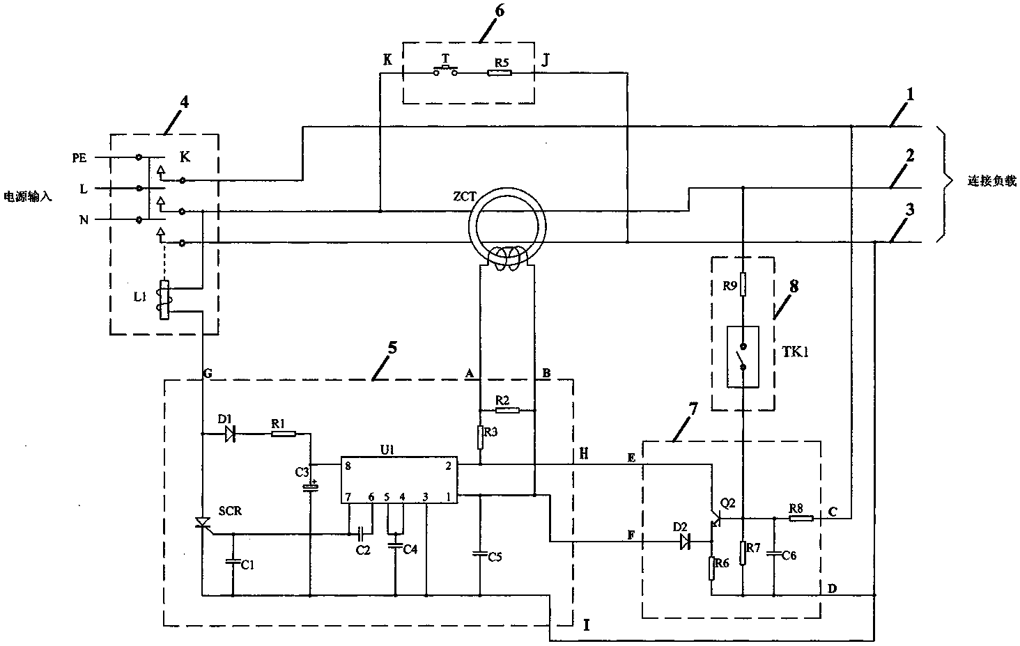
[0016] see figure 2 A leakage protection device with extended functions also includes a temperature protection circuit 8, the temperature protection circuit 8 includes a temperature protection switch TK1 and a resistor R9, one end of the temperature protection switch TK1 is connected to the base of the transistor Q2 in the function expansion circuit 7 pole, one end of resistor R7, one end of capacitor C6 and one end of resistor R8, the other end of temperature protection switch TK1 is connected to one end of resistor R9, and the other end of resistor R9 is connected to phase line 2 passing through the zero-sequence current transformer. When the temperature reaches the operating temperature of the temperature protection switch TK1, the temperature protection switch TK1 is closed and turned on, the voltage of the phase line 2 is added to the base of the transistor Q2 through the resistor R9, and the transistor Q2 is turned on, so that the integrated chip in the IC drive circuit ...


PUM


Abstract

The invention discloses a leakage protection device with an extended function, belonging to the field of a low-voltage power distribution protection device. The leakage protection device comprises a zero-sequence current transformer, a release, an IC (integrated circuit) drive circuit, a test circuit and a function extension circuit; wherein the release is connected with a power grid, and a phase line, a zero line and an earth wire are led to supply electricity to a load; one end of an electromagnet coil of the release is connected with the G end of the IC drive circuit, and the other end of the electromagnet coil of the release is connected with the phase line which does not pass through the zero-sequence current transformer; one end of a secondary coil of the zero-sequence current transformer is connected with the A end of the IC drive circuit, and the other end of the secondary coil of the zero-sequence current transformer is connected with the B end of the IC drive circuit; the H end of the IC drive circuit is connected with the output end of the function extension circuit; the B end of the IC drive circuit is connected with a reference voltage input end of the function extension circuit; the K end of the test circuit is connected with the phase line which does not pass through the zero-sequence current transformer, and the input end of the function extension circuit is connected with the earth wire. The leakage protection device can provide immediate protection to abnormal electrification of the earth wire of the power grid or electrification of a housing of an electric appliance, and the temperature rise protection is achieved.

Description

technical field [0001] The invention belongs to the technical field of low-voltage power distribution protection devices, and relates to a leakage protection device, in particular to a leakage protection device with extended functions. Background technique [0002] Since the invention and use of electricity by human beings, electricity has not only brought a lot of convenience to human beings, but also brought many disasters to human beings. At present, the proportion of non-compliance in the safety of the electricity environment in our country is still very high, and there are still many potential safety hazards. If the electrical power supply wiring is incorrect, there is no grounding or poor grounding, the use of inferior sockets, and the ground wire of the power supply is abnormally charged, etc., the electrical shell will be charged, resulting in electric shock accidents. So when all kinds of electrical appliances come one after another, all kinds of protection devices...

Claims


Application Information

Patent Timeline
Patent Type & Authority Patents(China)
IPC IPC(8): H02H3/32H02H5/04
Inventor 章祖德
Owner 常熟市立得电器有限公司
Learn More