
Built-in permanent magnet motor rotor and permanent magnet motor with rotor

A permanent magnet motor, built-in technology, applied in the direction of magnetic circuit rotating parts, magnetic circuit shape/style/structure, etc., can solve the problems of large torque fluctuation, low overload capacity, poor reliability, etc., to improve the salient pole ratio , the effect of reducing magnetic flux leakage and reducing loss

Inactive Publication Date: 2012-09-19
浙江西子富沃德电机有限公司
View PDF4 Cites 4 Cited by
  • Summary
  • Abstract
  • Description
  • Claims
  • Application Information

AI Technical Summary

Problems solved by technology

However, the current traditional built-in permanent magnet motors have large torque fluctuations, low overload capacity, large volume, high noise, and relatively poor reliability.

Method used


Image

  • Built-in permanent magnet motor rotor and permanent magnet motor with rotor
  • Built-in permanent magnet motor rotor and permanent magnet motor with rotor
  • Built-in permanent magnet motor rotor and permanent magnet motor with rotor

Examples


Embodiment Construction

[0021] In order to make the object, technical solution and beneficial technical effect of the present invention clearer, the technical content and specific implementation methods of the present invention will be further described in detail below in conjunction with the accompanying drawings. It should be understood that the specific implementations described in this specification are only for explaining the present invention, not for limiting the present invention.

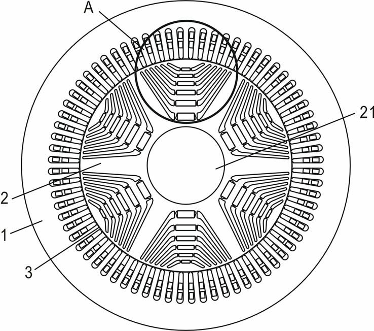
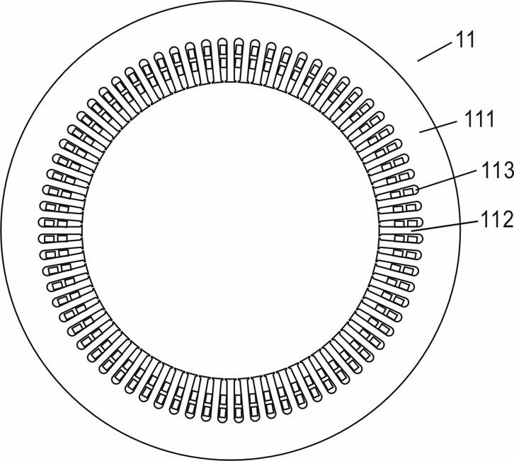
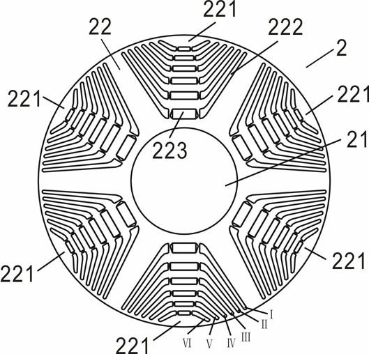
[0022] refer to Figure 1 to Figure 4 As shown, the interior permanent magnet motor of the embodiment of the present invention includes a casing, a stator 1 and a rotor 2 installed inside the casing, and a narrow air gap 3 is left between the stator 1 and the rotor 2 . The stator 1 includes a stator core 11 fixed on the inner wall of the casing and a stator winding. The stator core 11 includes a stator yoke 111, stator teeth 112 and stator slots 113; The rotor core 22. A selectable number of magnetic poles 221 a...


PUM


Abstract

The invention provides a built-in permanent magnet motor rotor which comprises a rotation shaft (21) and a rotor core (22). Magnetic poles (221) are evenly arranged on the rotor core (22), each magnetic pole (221) is provided with at least two groups of magnetic resistance grooves (222), each group of magnetic resistance groove(222) penetrates through the rotor core (22) in the axial direction, each group of magnetic resistance groove(222) comprises a left hollow groove and a right hollow groove which are symmetrical, and a permanent magnet (223) is arranged in the symmetric center of the symmetrical hollow groove of at least one group of magnetic resistance grooves. The invention further provides a permanent magnet motor. Compared with the prior art, the built-in permanent magnet motor rotor improves salient pole ratio of the motor, greatly increases reluctance torque of the motor, reduces torque pulsation and lowers motor cost.

Description

technical field [0001] The invention belongs to the technical field of motors, in particular to a built-in permanent magnet motor rotor and a permanent magnet motor using the rotor. Background technique [0002] The reluctance torque of the permanent magnet motor mainly comes from the salient pole effect of the motor. The reluctance torque refers to the force that the permanent magnet poles receive as the rotor of the motor in the direction of the small reluctance. The reluctance torque is determined by the rotor magnetic circuit. due to structural asymmetry. According to the permanent magnet structure, permanent magnet synchronous motors can be divided into surface permanent magnet synchronous motors and built-in permanent magnet synchronous motors. Compared with surface permanent magnet motors, built-in permanent magnet motors have simpler production processes; The surface is smooth, the air gap between the stator and the rotor is relatively uniform, which is more conduci...

Claims


Application Information

Patent Timeline
Patent Type & Authority Applications(China)
IPC IPC(8): H02K1/27
Inventor 罗昊杨志华李创平辛懋
Owner 浙江西子富沃德电机有限公司
Learn More