Method for cooling turbine stators and cooling system for implementing said method

A technology of cooling system and cooling method, which is applied in the direction of stator, blade support element, machine/engine, etc., and can solve the problem of air-conditioning performance cost and so on

Inactive Publication Date: 2012-09-19
TURBOMECA SA
View PDF8 Cites 8 Cited by
  • Summary
  • Abstract
  • Description
  • Claims
  • Application Information

AI Technical Summary

Problems solved by technology

The exhaust then causes the reintroduction of hot air and prevents cooling of the stator
[0004] Also, ther

Method used


Image

  • Method for cooling turbine stators and cooling system for implementing said method
  • Method for cooling turbine stators and cooling system for implementing said method
  • Method for cooling turbine stators and cooling system for implementing said method

Examples


Embodiment Construction

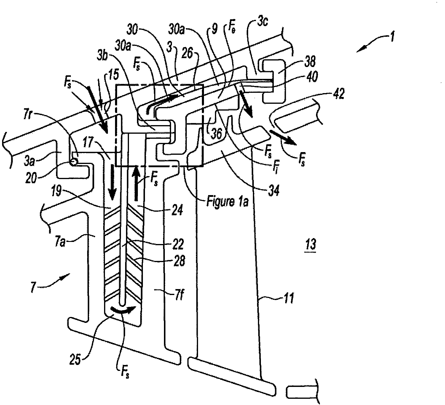
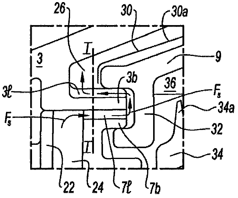
[0035] The terms "inner" and "outer" define components viewed from one side of the axis of rotation of the turbine or from the opposite side of this axis. Furthermore, the same reference numerals in the drawings denote the same or equivalent components.

[0036] With reference to 1, the turbine 1 consists in particular in a housing 3 of an air distribution stator or distributor with fixed vanes 7, a seal ring support 9 for the movable vanes 11, and a nozzle (not shown) for reaching the The exit path 13 is composed. The housing 3 fixes the position of the dispenser and ring support with support arms 3a, 3b and 3c. Air under the cowling is drawn in at low pressure in the form of an airflow Fs, across the inlet aperture 15 of the housing 3 and up through the distributor 7 and ring support 9 to the outlet path 13 .

[0037] The holes 15 are arranged facing an air inlet 17 provided at one end of a first radial circulation channel 19 inside the distributor 7 . The upstream seal o...


PUM


Abstract

The invention relates to a method and system for cooling turbine engine turbines (1), said method and system comprising: at least one pair of parts to be cooled, said pair consisting of a stator, upstream from the stator valve (7), and a sealing ring mounting (9) of a downstream movable blade rotor (11) that is adjacent to the stator (7); a turbine housing (3); and an outlet path (13). Said system in particular comprises: at least one opening (15) in the housing (3) facing at least one part (7, 9) to be cooled; and an air circuit producing a forced convection (19, 24, 26, 30) in connection with said parts (7, 9) and at least one downstream outlet (56) in the path (13) so as to draw in and transport an ambient air flow (Fs).

Description

technical field [0001] The invention relates to a method of cooling stators, distributors or rings of gas turbines equipped on aircraft propulsion turbines, especially helicopters, and to a cooling system for implementing the method. Background technique [0002] The increasing temperature of the turbine thermodynamic cycle necessitates the extension of the cooler to the stator part of the turbine: the stationary vanes of the turbine's distributor, and the smooth or seal ring support of the movable blades or rotor (hereinafter referred to as ring support). Air is then introduced across the vanes of the distributor and then introduced over the rotor ring. Next, air is reintroduced into the exit path. [0003] Next, the outlet nozzle has a coefficient of restitution (Cp) at low speeds that can reach negative values, which results in a reversal of the pressure difference between the atmosphere and the outlet plane of the turbine. Exhaust then causes reintroduction of hot air...

Claims


Application Information

Patent Timeline
IPC IPC(8): F01D5/18F01D9/06
CPCF05B2220/309F05B2220/3025F05B2260/205F05D2220/329Y02T50/676Y02T50/67F05D2220/3215F01D5/187F05D2260/205F01D9/065Y02T50/60F01D5/18F01D9/06
Inventor 丹尼斯·卢克·艾伦·查特罗普曼纽尔·飞利浦·吉恩·皮埃尔
Owner TURBOMECA SA
Why Eureka
Try Eureka