Bobbin tray

A technology for trays and bobbins, which is applied to spinning machines, textiles, papermaking, and splicing devices. It can solve problems that affect the success rate of threading, failure to blow out, and threading failure after tube replacement, and achieve low production costs and high efficiency. High success rate and tube replacement success rate

Inactive Publication Date: 2012-09-26
QINGDAO HONGDA TEXTILE MACHINERY
View PDF7 Cites 5 Cited by
  • Summary
  • Abstract
  • Description
  • Claims
  • Application Information

AI Technical Summary

Problems solved by technology

The disadvantage of this structure is: Too much brush density will affect the negative pressure airflow, thereby affecting the success rate of spinning. If the brush density is too small, there will be a large gap, and the tail yarn will still be wound on the belt, and the brush There are many burrs at the end of the tube. When the tail yarn is concentrated at the brush, it is easy to get entangled with the burrs, so that the yarn tail cannot be blown by blowing after the tube change, resulting in the failure of the tube change.

Method used


Image

  • Bobbin tray
  • Bobbin tray
  • Bobbin tray

Examples


Embodiment Construction

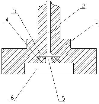
[0019] see figure 1 , figure 2 , an embodiment of a bobbin tray with a filter screen in the present invention, comprising: a tray body 1, a central hole 2 is arranged on the upper part of the tray body 1, a bottom hole is opened in the middle of the bottom surface of the tray body 1, and the diameter of the bottom hole is larger than the center hole 2 The aperture, and communicate with the central hole 2. A circular filter screen 3 consistent with the diameter of the bottom hole is set in the bottom hole and the near end of the central hole 2, and an annular jacket 4 is installed below the circular filter screen 3 to fix the circular filter screen 3. The outer diameter of the annular jacket 4 is slightly larger than the diameter of the bottom hole, and the annular jacket 4 and the bottom hole are tightly fitted and installed.

[0020] The bottom hole on the bottom surface of the tray body 1 is a stepped hole, and the diameter 6 of a section of the stepped hole near the bott...


PUM


Abstract

The invention provides a bobbin tray. The bobbin tray comprises a tray body, wherein a central hole is formed in the upper part of the tray body; a bottom hole is formed in the middle of the bottom surface of the tray body; the aperture of the bottom hole is greater than that of the central hole; and the bottom hole is communicated with the central hole. The bobbin tray is characterized in that a circular filtering screen of which the diameter is consistent with the aperture of the bottom hole is arranged at the end in the bottom hole, which is combined with the central hole; and a circular jacket is mounted below the circular filtering screen. The bottom hole on the bottom surface of the tray body is a stepped hole; and the aperture of one section of stepped hole, which is close to the bottom surface of the tray body, is greater than the aperture of one section, close to the lower end of the central hole, of the stepped hole. Tail yarns sucked into the central hole of a bobbin are long enough and are prevented from being wound; and meanwhile, the influence on the flowing of negative-pressure air current is avoided and the success rate of a tube exchange repiece is increased. In addition, the bobbin tray has the advantages of low cost and convenience and reliability in use.

Description

technical field [0001] The invention belongs to the technical field of textile machinery, and relates to an improvement of an accessory of spinning equipment, specifically a bobbin tray. Background technique [0002] The bobbin tray is mainly used for bobbin changing, the bobbin is inserted on the pallet, the tail yarn is sucked into the center hole of the bobbin, and the bobbin and the pallet are transported to various parts of the equipment by the belt. When changing tubes, the compressed air will pass through the hole at the bottom of the tray to blow the tail yarn in the bobbin out of the bobbin, and the blown tail yarn will be caught by the small suction nozzle, then the tube changing is successful. In order to improve the success rate of tube replacement, the longer the tail yarn sucked into the bobbin, the better. However, if the length of the tail yarn exceeds the bottom of the tray, it will be wound on the belt due to the movement of the belt, just like a hand. The...

Claims


Application Information

Patent Timeline
Patent Type & Authority Applications(China)
IPC IPC(8): D01H15/00D01H9/02
Inventor 姚水莲车社海赵云波薛成海
Owner QINGDAO HONGDA TEXTILE MACHINERY
Why Eureka
Try Eureka