
Method for preventing and detecting winding of buoyant cable

A technology of floating cables and cable reels, which is applied in the direction of using electric/magnetic devices to transmit sensing components, public buildings, gymnasiums, etc., and can solve problems such as automatic charging, long time for cleaning swimming pools, entanglement and knotting of umbilical cord cables, etc. , to achieve the effect of environmental protection of equipment, convenient manual intervention, and avoiding winding and knotting

Active Publication Date: 2014-06-04
HANGZHOU GAOYUE TECH
View PDF8 Cites 0 Cited by
  • Summary
  • Abstract
  • Description
  • Claims
  • Application Information

AI Technical Summary

Problems solved by technology

However, this method has the following disadvantages: First, the rechargeable floating power supply still needs to be connected with an umbilical cable and an automatic cleaning machine. Second, the charging capacity of the rechargeable floating power supply is generally relatively low, the charging time is generally not less than 4 hours, and the working time after being fully charged is generally 1 to 4 hours. The swimming pool with a large cleaning area needs to be charged repeatedly. However, the automatic cleaning machine cannot be automatically charged in the swimming pool water. On the one hand, it takes a long time to clean the swimming pool. At present, the cost of the rechargeable floating power supply is relatively high, which increases the stand-alone cost of the automatic cleaning machine, which is not conducive to user acceptance; Fourth, the rechargeable floating power supply needs to be completely sealed and waterproof, which puts forward higher requirements for the sealed and waterproof structure of the floating power supply; Fifth, the battery in the rechargeable floating power supply is not conducive to environmental protection when the machine is scrapped

Method used


Image

  • Method for preventing and detecting winding of buoyant cable
  • Method for preventing and detecting winding of buoyant cable
  • Method for preventing and detecting winding of buoyant cable

Examples


Embodiment Construction

[0046] The specific implementation manners of the present invention will be described in detail below in conjunction with the accompanying drawings.

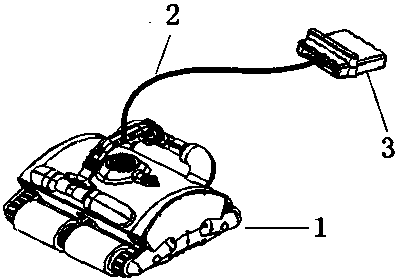
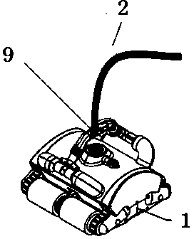
[0047] like figure 2 As shown, the device of the present invention includes an automatic cleaning machine 1, a floating cable 2, a power controller 3, and a cable reel device 4.

[0048] Automatic cleaning machine 1 is made up of two parts of arc-shaped main body structure and outlet handle.

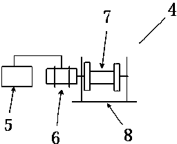
[0049] Wherein the cable reel device 4 is composed of a motor controller 5, a 24VDC DC motor 6, a reel 7, and a bracket 8. The DC motor 6 and the reel 7 are coaxially connected, and the motor controller 5 controls the DC motor 6 to drive the reel 7 forward. Or reverse rotation, the DC motor 6 controls the moment and direction of rotation of the floating cable 2 reel 7, when the automatic cleaning machine 1 is working, if the position away from the power box is getting farther and farther away, the reel slowly releases the floating cable ...


PUM


Abstract

The invention discloses a method for preventing and detecting the winding of a buoyant cable, comprising the following steps of: 1) a step of preventing the buoyant cable from being wound and knotted and 2) a step of detecting the winding and the knotting of the buoyant cable, wherein the step of preventing the buoyant cable from being wound and knotted comprises the following steps that when an automatic washing robot sends a forward or backward signal to a motor controller of a cable drum device arranged on the automatic washing robot, the cable drum device arranged on the automatic washing robot receives a corresponding signal and then controls a direct-current motor of the cable drum device to rotate, so as to keep the same unreeling / reeling of the buoyant cable as the automatic washing robot. According to the method disclosed by the invention, a bank-side power supply box supplies power and the working time and a power supply capacity of the automatic washing robot are not limited, so that a trouble of repeatedly and manually charging and discharging a buoyant power supply for a plurality of times is saved, and the buoyant cable is prevented from being wound and knotted and the winding and the knotting of the buoyant cable are detected.

Description

technical field [0001] The invention relates to an automatic cleaning robot for swimming pools, in particular to a method for protecting and detecting floating cables in the automatic cleaning robot for swimming pools. Background technique [0002] It is generally hoped that the swimming pool automatic cleaning robot (hereinafter referred to as the automatic cleaning machine) will work automatically in the process of cleaning the bottom and side walls of the swimming pool, with as little human intervention as possible. Due to the uninterrupted movement of the automatic cleaning machine, the general power supply scheme is to configure the power control box on the shore of the swimming pool, and connect the power control box and the automatic cleaning machine with a floating cable to provide power for the automatic cleaning machine. The schematic diagram is as follows figure 1 shown. However, a problem caused by the use of floating cables for power supply is that the floating...

Claims


Application Information

Patent Timeline
Patent Type & Authority Patents(China)
IPC IPC(8): E04H4/16G01D5/14
Inventor 万长明傅丹徐肇松
Owner HANGZHOU GAOYUE TECH
Learn More