Slipping luffing mechanism for crossbeam of horizontal directional drilling machine

A technology of horizontal directional drilling rig and luffing mechanism, which is applied in the direction of drilling equipment, earthwork drilling and production, supporting devices, etc. It can solve problems such as unstable operation, left and right shaking, and beam distortion, and achieve stable and reliable operation and increase climbing Angle, overcoming unstable effects

Inactive Publication Date: 2012-09-26
JIANGSU GOODENG ENG MACHINERY ASSEMBLING
View PDF6 Cites 6 Cited by
  • Summary
  • Abstract
  • Description
  • Claims
  • Application Information

AI Technical Summary

Problems solved by technology

[0002] When the horizontal directional drilling rig loads the drill pipe box, it will cause serious unbalanced load on the beam. The front end of the luffing mechanism of the old horizontal directional drilling rig is supported by double oil cylinders. The parallelogram linkage mechanism is very unstable, it will shake from side to side when walking, and the operation is not stable. Long-term use will cause the beam to be twisted and severely deformed.

Method used


Image

  • Slipping luffing mechanism for crossbeam of horizontal directional drilling machine
  • Slipping luffing mechanism for crossbeam of horizontal directional drilling machine
  • Slipping luffing mechanism for crossbeam of horizontal directional drilling machine

Examples


Embodiment Construction

[0011] The specific content of the present invention will be described in detail below in conjunction with the accompanying drawings and specific embodiments.

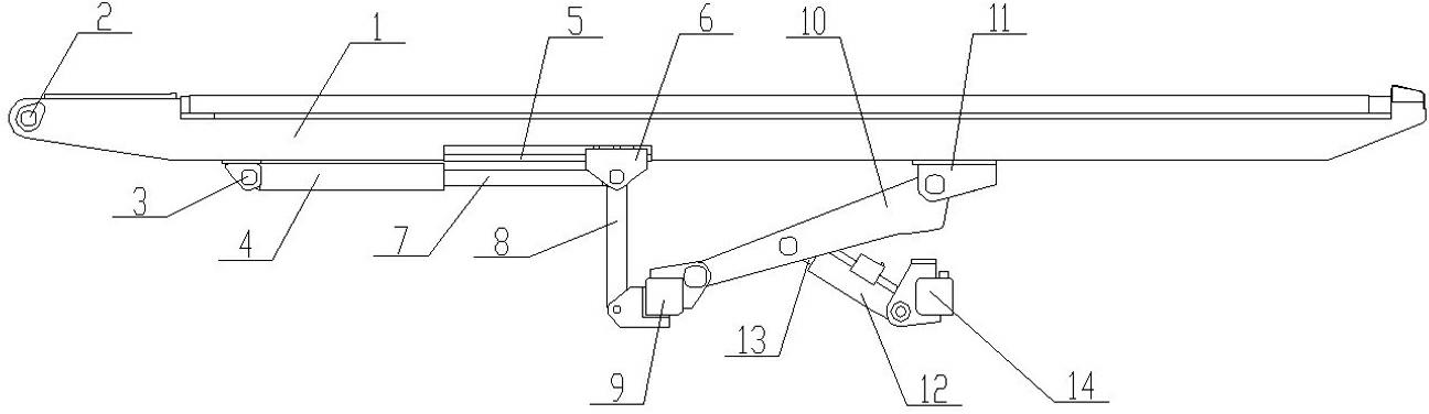
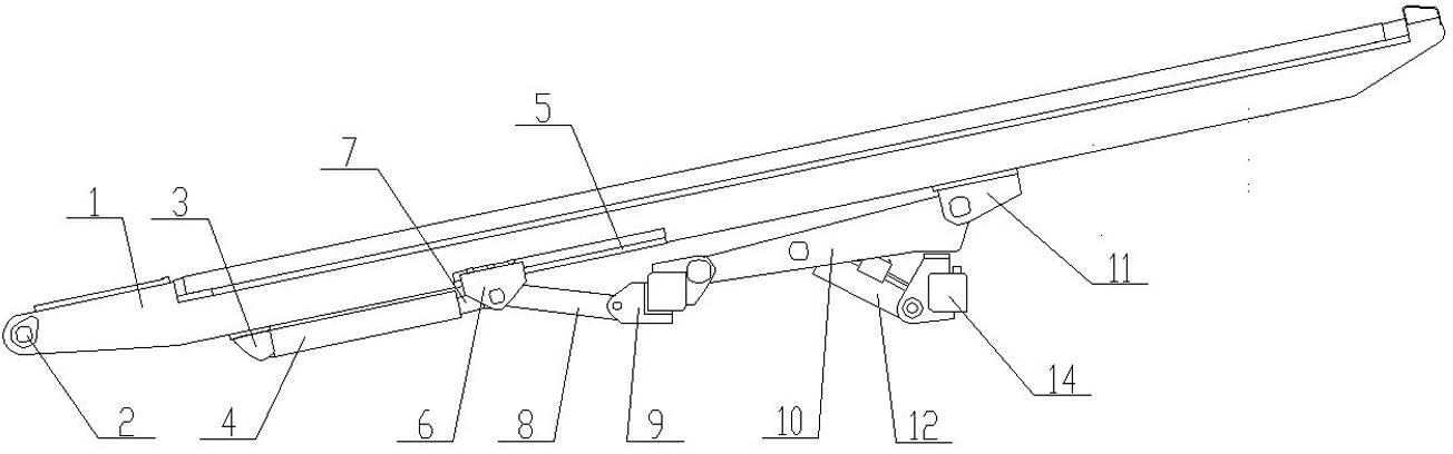
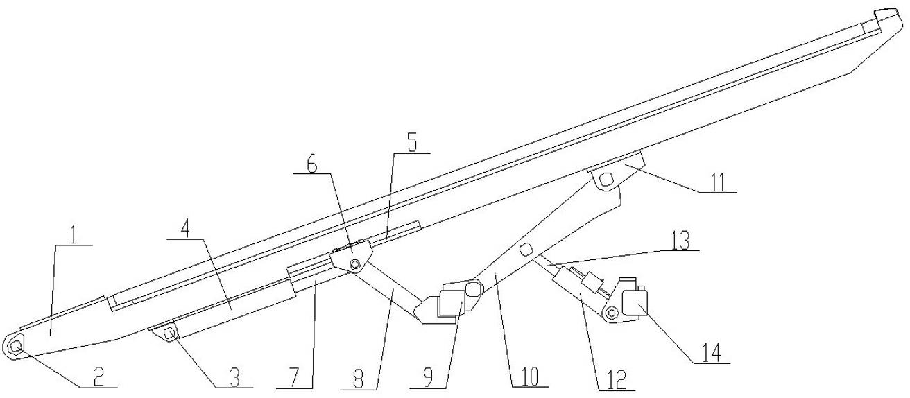
[0012] Such as figure 1 , figure 2 , image 3 As shown, the girder sliding luffing mechanism of the horizontal directional drilling rig includes: the girder 1, one end of the girder 1 is arranged on the chassis of the horizontal directional drilling rig through the fixing hole 2 and the bolt, and the lifting cylinder 4 is connected to the girder 1 through the hinge 3, A guide rail 5 is provided on the girder 1, and a sliding winch 6 is slidably arranged on the guide rail 5. The sliding winch 6 is respectively connected with the piston rod 7 of the lifting cylinder 4 and one end of the lifting connecting rod 8, and the lifting connecting rod 8 The other end of the connecting rod hinge seat 9 is connected with one end of the connecting rod hinge seat 9, and the other end of the connecting rod hinge seat 9 is connected...


PUM


Abstract

The invention discloses a slipping luffing mechanism for a crossbeam of a horizontal directional drilling machine. The slipping luffing mechanism comprises a crossbeam, wherein one end of the crossbeam is arranged on a chassis of the horizontal directional drilling machine through a fixing hole and a bolt; a lifting oil cylinder is connected with the crossbeam through a hinge; a guide rail is arranged on the crossbeam; a slipping hinged seat is arranged on the guide rail in a sliding manner and is respectively with a piston rod of the lifting oil cylinder and one end of a lifting connecting rod; the other end of the lifting connecting rod is connected with one end of a connecting rod hinged seat; the other end of the connecting rod hinged seat is connected with one end of a crossbeam connecting rod; the other end of the crossbeam connecting rod is arranged on the crossbeam through a hinge connecting seat; the middle of the crossbeam connecting rod is connected with the piston rod of the crossbeam oil cylinder; and the crossbeam oil cylinder is arranged on the chassis of the horizontal directional drilling machine through a connecting seat. The slipping luffing mechanism has the advantages of simple structure, low manufacturing cost, reliable and stable operation and strong practicability, and not only overcomes the defect of instability of the conventional luffing mechanism, but also can entirely lift the crossbeam to enlarge an climbing angle during transportation.

Description

technical field [0001] The invention relates to a horizontal directional drilling machine, in particular to a beam sliding luffing mechanism of the horizontal directional drilling machine. Background technique [0002] When the horizontal directional drilling rig loads the drill pipe box, it will cause serious unbalanced load on the beam. The front end of the luffing mechanism of the old horizontal directional drilling rig is supported by double oil cylinders. The parallelogram linkage mechanism is very unstable, it will shake from side to side when walking, and the operation is not stable. Long-term use will cause the girder to be twisted and severely deformed. Contents of the invention [0003] The technical problem to be solved by the present invention is to provide a horizontal directional drilling rig beam sliding luffing mechanism with stable and reliable operation. [0004] In order to solve the above-mentioned technical problems, the technical solution adopted in ...

Claims


Application Information

Patent Timeline
Patent Type & Authority Applications(China)
IPC IPC(8): E21B15/04
Inventor 陈凤钢
Owner JIANGSU GOODENG ENG MACHINERY ASSEMBLING
Why Eureka
Try Eureka