
LED lamp

A technology of LED lamps and LED light sources, applied in lighting devices, cooling/heating devices of lighting devices, light sources, etc., can solve the problem of unbiased heat dissipation of PCB boards, achieve a concise overall structure, ensure work reliability, and is conducive to The effect of manufacturing and assembly

Active Publication Date: 2012-09-26
江苏山水节能服务股份有限公司
View PDF17 Cites 4 Cited by
  • Summary
  • Abstract
  • Description
  • Claims
  • Application Information

AI Technical Summary

Problems solved by technology

[0006] And, the "active cooling LED chandelier" introduced by the authorized announcement number CN201819125U has made achievements in the heat dissipation of LED light source (patent called LED module), but it is also biased in the heat dissipation of PCB board (patent called control circuit)

Method used


Image

  • LED lamp
  • LED lamp
  • LED lamp

Examples


Embodiment 1

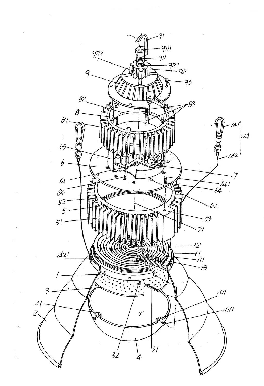
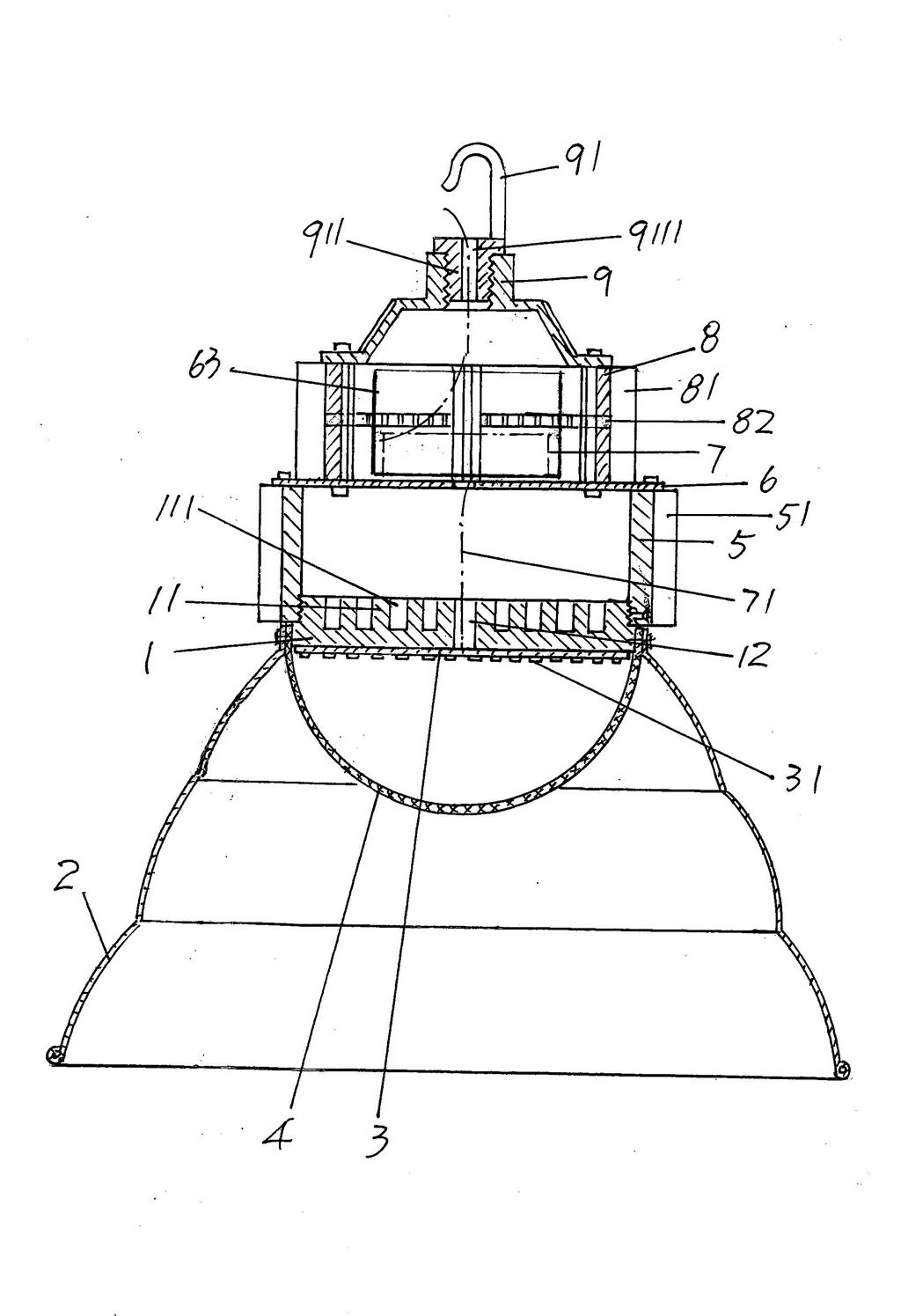
[0025] See figure 1 with figure 2 , A lamp holder 1 in the shape of a disc is given. In the state of use of the lamp holder 1, the surface on the upward side is formed with an annular ring that gradually expands outward from the center and protrudes from the surface of the lamp holder 1. The radiating strip 11, the gradually expanding from the center here refers to the diameter of the radiating strip 11 gradually increasing from the center of the lamp holder 1, and the recessed area between the adjacent radiating strips 11 constitutes the radiating cavity 111 . Of course, the structural form of the heat dissipation strip 11 is not limited to the structural form shown in the figure. For example, it may be a group of strip-like structures distributed at intervals and protruding from the surface of the lamp holder 1, or other similar structures. Therefore, the solution of the present invention cannot be limited by the change of the form of the heat sink 11.

[0026] A wire tran...

Embodiment 2

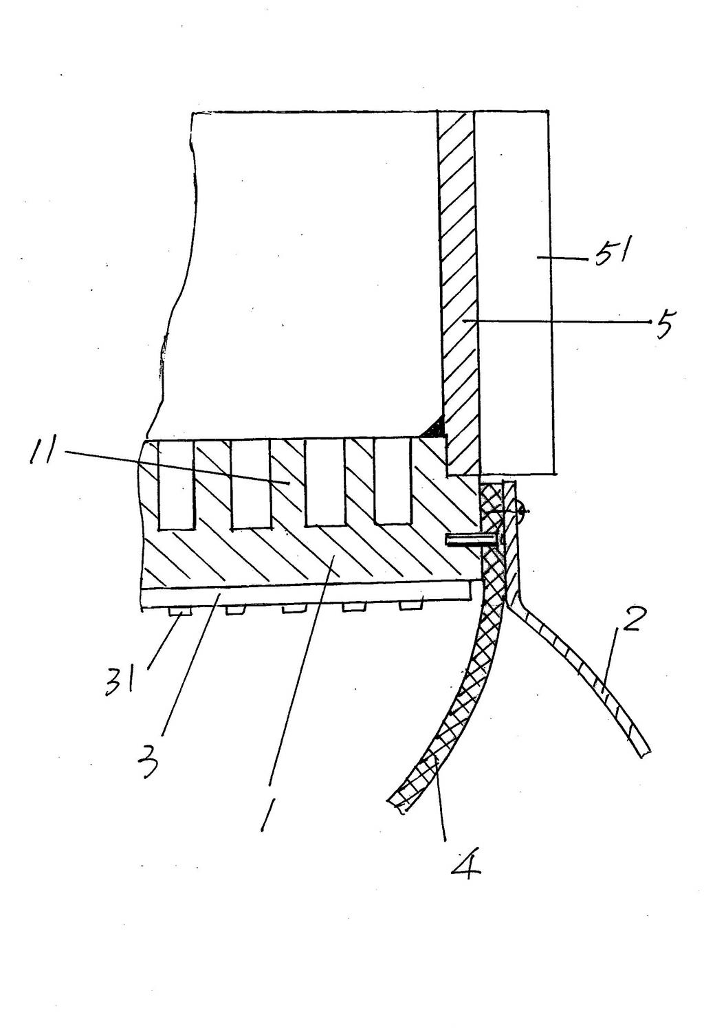
[0036] See image 3 As another form of the present invention, the first heat dissipation sleeve 5 is connected to the lamp holder 1 by welding, so that the lamp holder fitting thread 13 on the lamp holder 1 and the heat dissipation sleeve on the first heat dissipation sleeve 5 can be eliminated. Connect the thread 52, and the rest are the same as the description of Embodiment 1.


PUM


Abstract

An LED lamp belongs to the technical field of illumination equipment, and includes a lamp holder, a lampshade, an LED light source plate, a diffusion cover, a first heat dissipation sleeve, a separation plate, an LED drive power supply, a second heat dissipation sleeve, and a tail cover, wherein heat dissipation strips are formed on the surface of one side, and a heat dissipation cavity is formed between every two adjacent heat dissipation strips; the lampshade is fixed with the lamp holder; the LED light source plate is fixed with the lamp holder, and an LED light source is arranged on the LED light source plate; the diffusion cover is fixed with the lamp holder; the first heat dissipation sleeve is matched and connected with the lamp holder, and first heat dissipation fins are formed on the outer wall; the separation plate is fixed with the first heat dissipation sleeve; the LED drive power supply is arranged on the separation plate, and is electrically connected with the LED light source; the second heat dissipation sleeve is fixed with the separation plate, second heat dissipation fins are formed on the outer wall, and the LED drive power supply corresponds to the inside of the cavity of the second heat dissipation sleeve; and the tail cover is fixed with the second heat dissipation sleeve and is equipped with a mounting pothook. The LED lamp has the advantages of prolonging the service life, ensuring the reliability of the LED drive power supply in work, and increasing the heat dissipation area to embody eddy type heat dissipation.

Description

technical field [0001] The invention belongs to the technical field of lighting equipment, and in particular relates to an LED lamp. Background technique [0002] Due to the advantages of high luminous efficiency, energy saving, long service life, green environmental protection and low maintenance workload, LED lamps are highly valued by people. There is no lack of technical information about LED lamps in the published Chinese patent documents. Such as CN201748219U (a multi-purpose LED lamp), CN201757302U (assembled LED lamp), CN201772302U (LED lamp), CN101984280A (LED lamp), CN201462616U (a LED chandelier), CN201731397U (ceiling hanging lamp structure), CN201568846U ( LED energy-saving factory chandelier), CN201187717Y (LED chandelier) and CN201819125U (active cooling LED chandelier), etc. [0003] As known in the industry, LED lamps will generate heat when they work. If the heat cannot be effectively diffused to the outside world, it will not only affect the service life,...

Claims


Application Information

Patent Timeline
Patent Type & Authority Applications(China)
IPC IPC(8): F21S2/00F21V29/00F21Y101/02F21K9/20F21V29/70F21V29/71F21V29/77F21Y115/10
Inventor 陈伟星
Owner 江苏山水节能服务股份有限公司
Learn More