Flow control method for solar heat collector system

A solar heat collector and system flow technology, applied in solar thermal power generation, solar thermal devices, heating devices, etc., can solve problems such as instability, frequency conversion of heat conduction oil pumps, etc., and achieve the effect of ensuring stability

Inactive Publication Date: 2012-09-26
YIKEBO ENERGY TECH SHANGHAI
View PDF6 Cites 12 Cited by
  • Summary
  • Abstract
  • Description
  • Claims
  • Application Information

AI Technical Summary

Problems solved by technology

[0006] The purpose of the present invention is to provide a flow control method for a solar thermal collector system to overcome the problem of instability of the solar thermal collector system in the prior art due to the frequency conversion of the heat conduction oil pump

Method used


Image

  • Flow control method for solar heat collector system
  • Flow control method for solar heat collector system

Examples


Embodiment Construction

[0015] The specific embodiments of the present invention will be described in detail below in conjunction with the accompanying drawings.

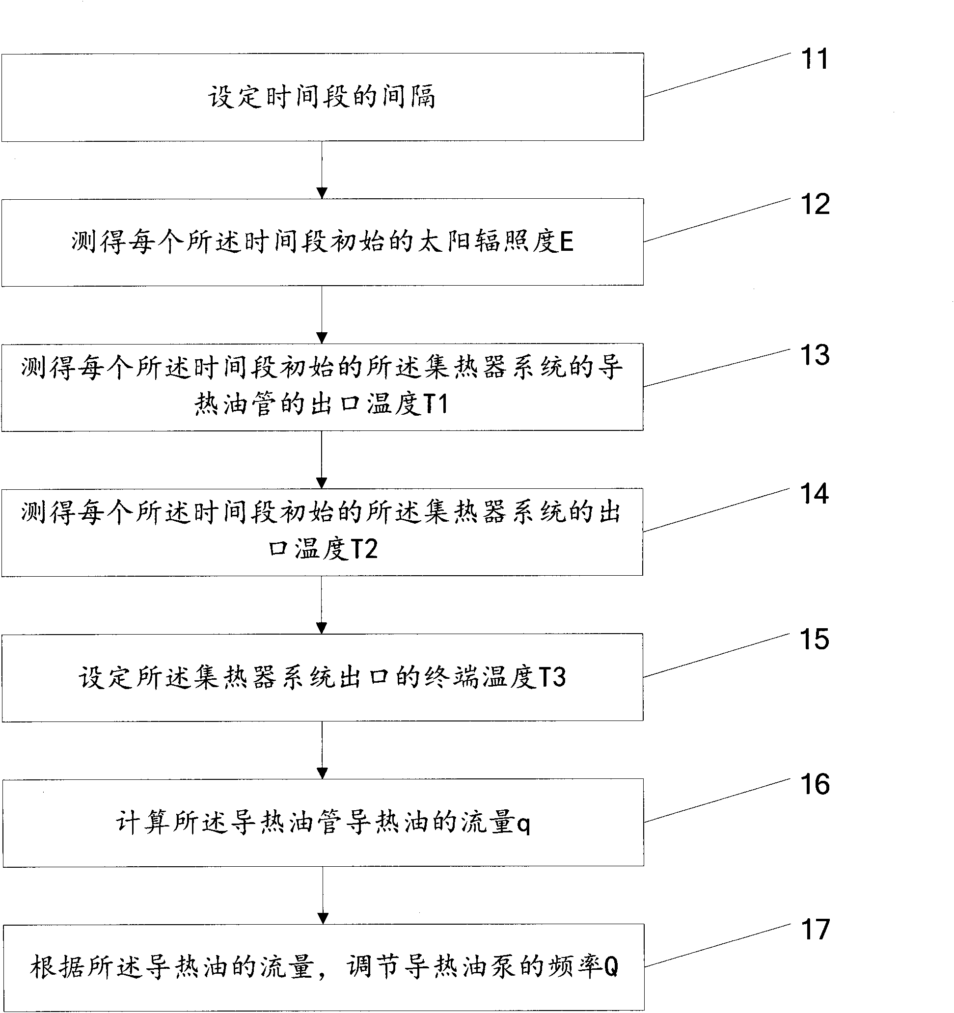
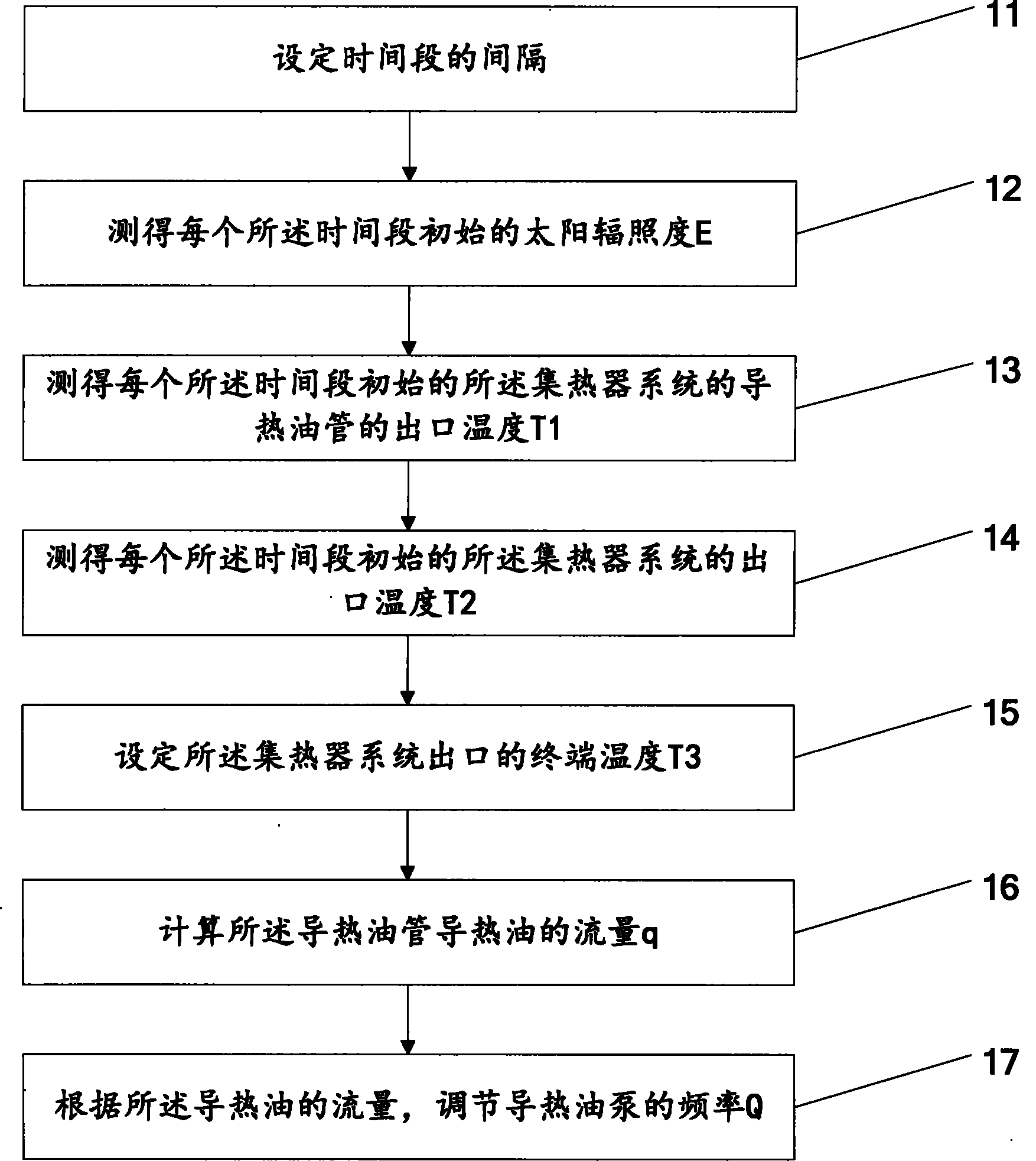
[0016] First, please refer to figure 1 , figure 1 It is a schematic flow chart of the solar heat collector system flow control method of the present invention, from figure 1 It can be seen that the solar heat collector system flow control method of the present invention comprises the following steps:

[0017] Step 11: Set the interval of the time period. The interval of the time period is 1 hour, 2 hours, 3 hours or 4 hours. The interval setting of the time period can be set according to the change of the season. For example, in summer, the illumination changes greatly , then the interval of the time period should be set smaller, for example, the interval of the time period is set to 1 hour, and the change of light in winter is small, the interval of the time period is set larger, for example, the interval of the time period is set to 4 ...


PUM


Abstract

The invention provides a flow control method for a solar heat collector system. The flow control method comprises the following steps: setting interval of a time period; determining the initial solar irradiance E of each time period; determining the initial temperature T1 of an outlet of a heat-conducting oil pipe of the heat collector system in each time period; determining the initial temperature T2 of the outlet of the heat collector system in each time period; setting the terminal temperature T3 of an outlet of the heat collector system; calculating the flow q of heat-conducting oil in the heat-conducting oil pipe; and according to the flow of heat-conducting oil, regulating the frequency Q of a heat-conducting oil pump. The flow control method for the solar heat collector system can maintain the frequency of the heat-conducting oil pump unchanged within a certain time period, thus improving the stability of the solar heat collector system.

Description

technical field [0001] The invention belongs to the field of solar energy equipment, and in particular relates to a flow control method of a solar heat collector system. Background technique [0002] The thermal energy utilization of concentrated solar energy usually has two forms. The first one is to collect and concentrate the sun (light) on a target, and convert thermal energy into mechanical energy through a Stirling Engine to directly drive a generator. The second form is the conversion of sunlight into heat through a collector, receiver, and heat transfer fluid, which can then be converted into electricity or directly used in other applications, such as cooling or heating. In such applications, Light energy collection efficiency and heat loss will determine the overall solar energy to thermal energy conversion efficiency. [0003] In the above-mentioned second application, the heat loss of the solar receiver depends on conduction heat loss, convective heat loss and bl...

Claims


Application Information

Patent Timeline
Patent Type & Authority Applications(China)
IPC IPC(8): F24J2/40
CPCY02E10/40
Inventor 项晓东蔡玮
Owner YIKEBO ENERGY TECH SHANGHAI
Why Eureka
Try Eureka