Check patentability & draft patents in minutes with Patsnap Eureka AI!

Multi-rotary absolute value rotary encoder

An absolute value, coding technology, applied in the field of sensors (encoders), can solve problems such as inability to meet needs, incomplete functions or performance, and high price

Inactive Publication Date: 2012-09-26
张维阳
View PDF5 Cites 10 Cited by
  • Summary
  • Abstract
  • Description
  • Claims
  • Application Information

AI Technical Summary

Problems solved by technology

[0007] Obviously, the problems that can be summarized in the current existing products are: there are more or less defects, either the function or performance is not perfect enough to meet the needs, or the price is expensive

Method used


Image

  • Multi-rotary absolute value rotary encoder
  • Multi-rotary absolute value rotary encoder
  • Multi-rotary absolute value rotary encoder

Examples


Embodiment 1

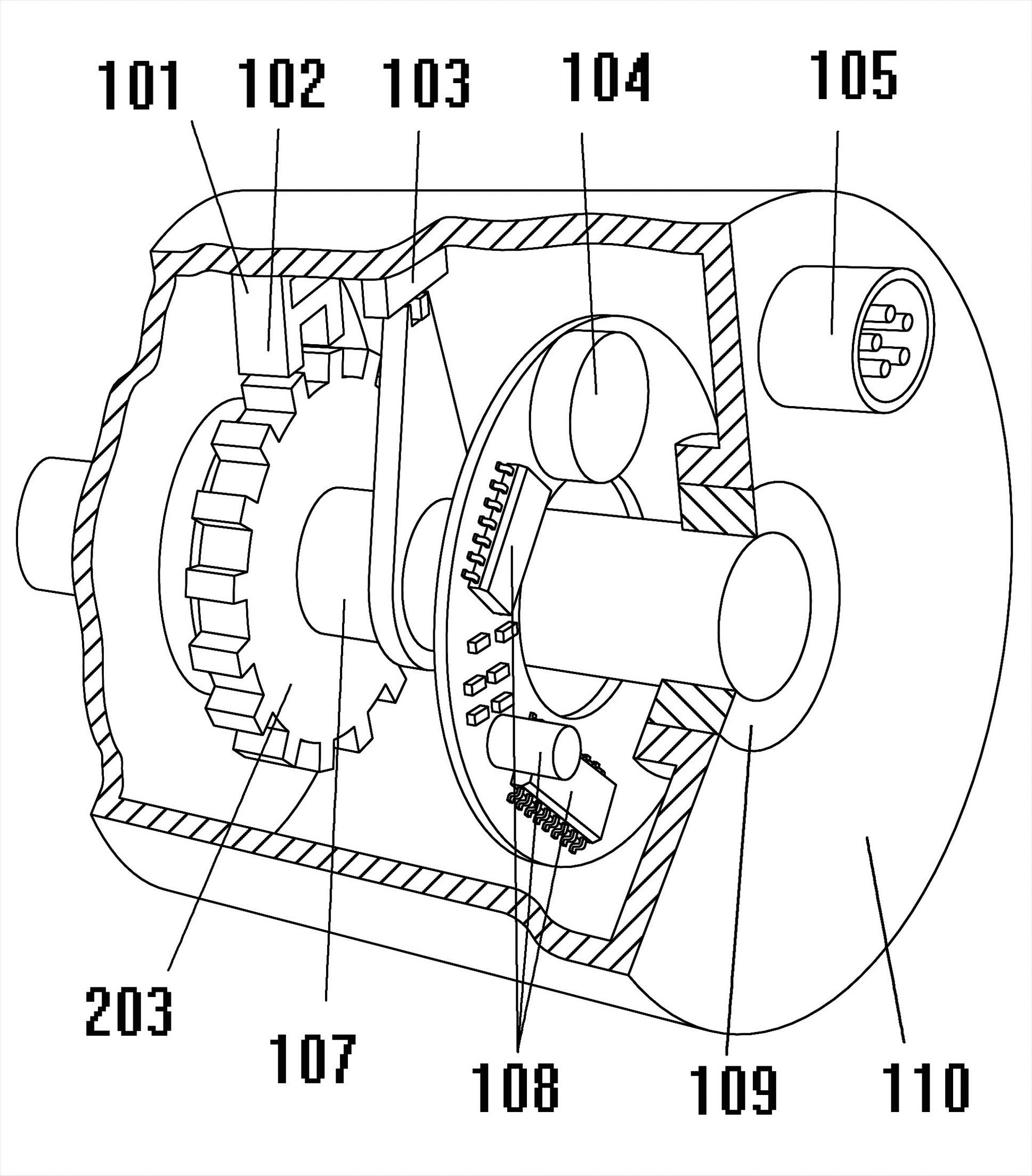
[0063] refer to figure 1 In addition to the necessary conventional structures such as the backup power supply 104, the data interface 105, the input shaft 107, the processing circuit 108, the bearing 109, and the housing 110, an active ferromagnetic component 203 with a raised structure is specially designed to fix the On the input shaft 107, rotating together with it, the ferromagnetic ratchet 203 drives a passive ferromagnetic sensor assembly 102, and among these two ferromagnetic assemblies, choose one (this illustration is in the ferromagnetic sensor assembly 102) Install the elastic damping energy storage structure 101.

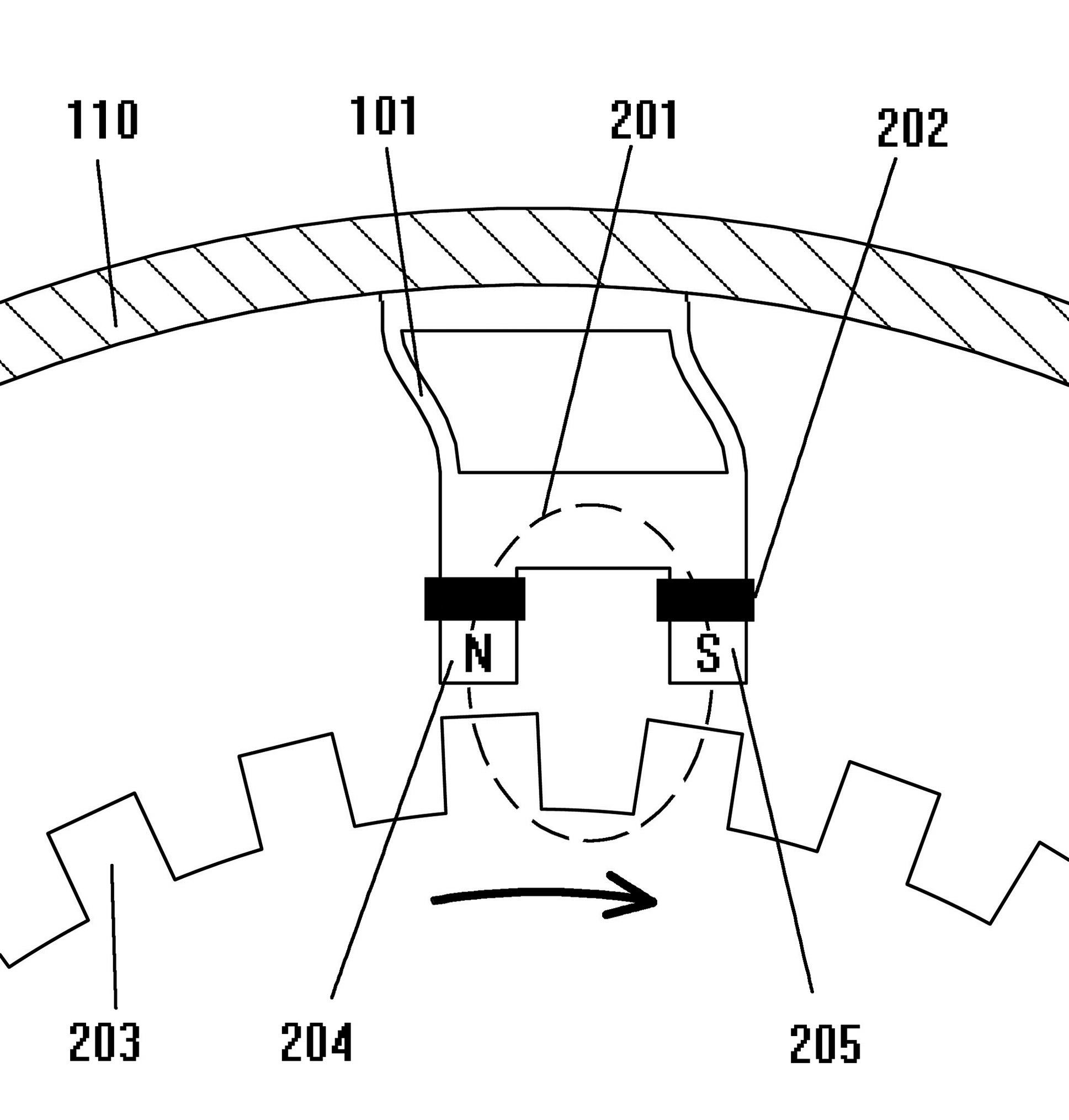
[0064] figure 1 For details near the ferromagnetic sensing assembly 102, see figure 2 , the ferromagnetic sensing component 102 is mainly composed of figure 2 Middle sensor coil 202, sensor N pole 204, sensor S pole 205

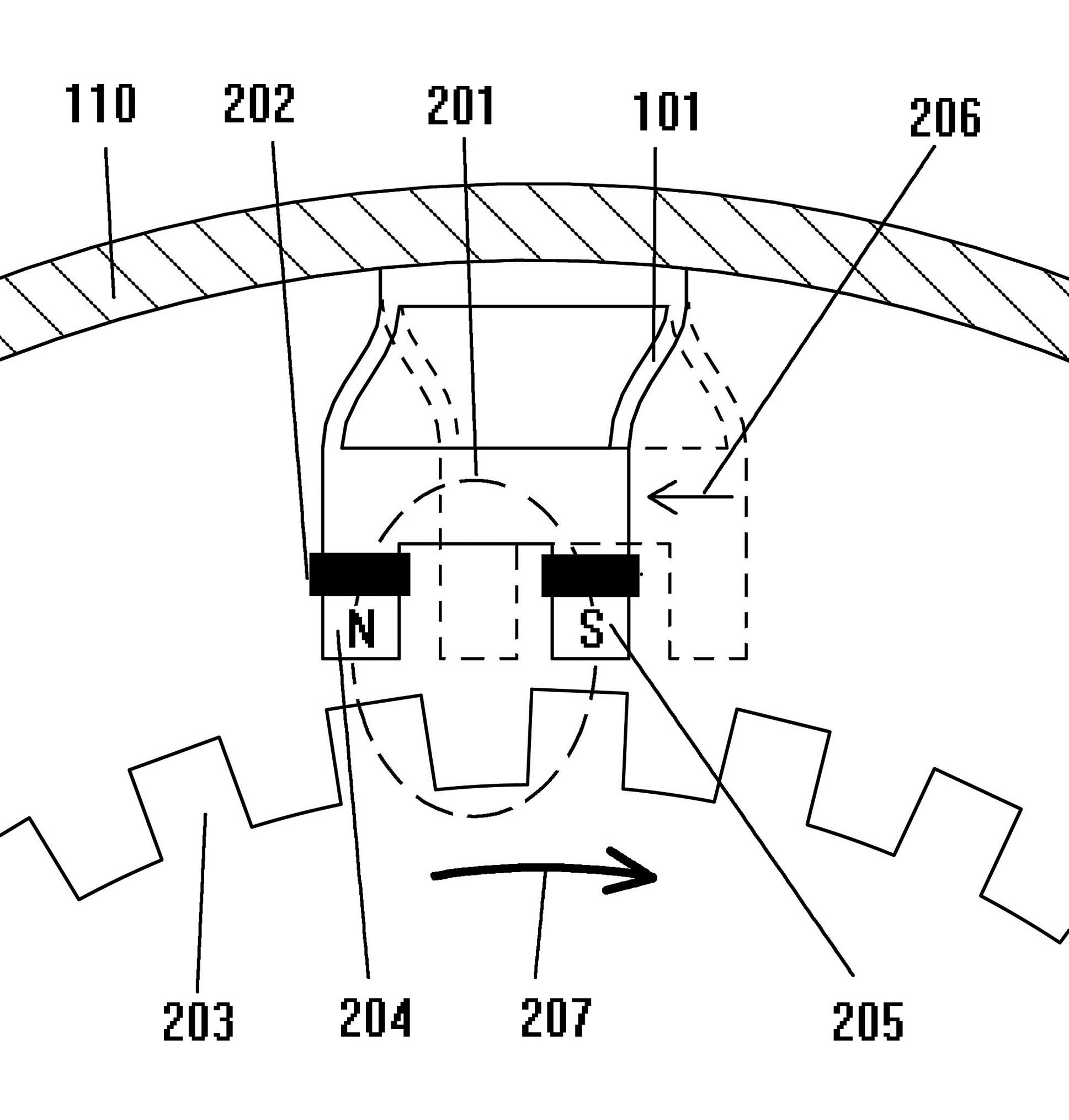
[0065] refer to image 3 , when the two ferromagnetic components 203 and 102 generate a relative motion trend, under the joint ...

Embodiment 2

[0067] Exemplary overall embodiment two (see Figure 4 ):

[0068] Most of them are consistent with Embodiment 1, only the sensing components are divided into two sets, which are respectively driven by two reversely installed one-way bearings 301, that is, one of the two ferromagnetic ratchets will only rotate clockwise with the input shaft, and the other It will only turn counterclockwise with the input shaft.

Embodiment 3

[0069] Exemplary overall embodiment three (see Figure 5 ):

[0070] Most of the structures are the same as the first embodiment, except that the type of the sensor has been changed. Here, the power generation capability of the piezoelectric ceramic 401 is used to realize the conversion of the displacement and the electric signal. When the cam 402 rotates one tooth, the piezoelectric sensing head will swing and knock once to output an electric pulse signal. In the actual implementation, because of the characteristic of vibration, the piezoelectric ceramic sensor can be installed in any sensitive part. The action diagram of this embodiment can be found in Figure 6 .


PUM


Abstract

The invention relates to a sensor for directly or indirectly measuring mechanical displacement, mainly aiming at the improvement of one type of multi-rotary (multi-ring) absolute value rotary encoders. The traditional technical design of the sensor has the disadvantages of large power consumption, complicated structure and high construction cost. According to the invention, an elastic energy storage mechanism 101 is added in an original structure creatively, so that a sensing assembly applying the technology does not need to be powered by an external power supply and also can spontaneously generate power, and even can output electric energy to be used by a signal processing circuit. The sensor which adopts the technology has final three direct beneficial effects: a cheap chip with lower power consumption can be used for replacing a previous complicated and precise structure, so that the cost is greatly reduced; an electronic chip is used for recording data so that a digit recording capability is greatly improved; and the application of a low-power-consumption chip group enables the sensor to not depend on the external power supply, and only an inner portable power supply can maintain more than several years of data recording.

Description

technical field [0001] The invention relates to a sensor (encoder) for measuring mechanical displacement. Displacement sensors are widely used, such as in the engine, for the positioning of the crankshaft rotation phase, the self-perception and control of the attitude of the assembly line manipulator, the quantitative meter counting of the production line, the dynamic or static positioning of each movement axis of the CNC machine tool, etc. It can often be seen even in daily life, such as elevators, printers, mice, gas meters, water meters and other metering instruments. Background technique [0002] At present, among the common mature products, there are three types according to the measurement range capability, namely: incremental type, single-turn absolute value type, and multi-turn absolute value type (many water meters, gas meters and other passive meters are also listed here) . According to the sensor form, there are magnetoelectric, magnetic sensitive and photoelect...

Claims


Application Information

Patent Timeline
IPC IPC(8): G01D5/14G01D5/245
Inventor 张维阳
Owner 张维阳
Features
  • R&D
  • Intellectual Property
  • Life Sciences
  • Materials
  • Tech Scout
  • Unparalleled Data Quality
  • Higher Quality Content
  • 60% Fewer Hallucinations
Learn More