Coding-decoding method based on communication of access control system

An encoding and decoding method and access control system technology, which are applied in the directions of instruments, time registers, individual input/output registers, etc.

Active Publication Date: 2012-09-26
KUANG CHI INTELLIGENT PHOTONIC TECH
View PDF1 Cites 35 Cited by
  • Summary
  • Abstract
  • Description
  • Claims
  • Application Information

AI Technical Summary

Problems solved by technology

Therefore, by combining the performance of the mobile phone and the single-chip microcomputer, through a specially set encoding method, the LED light of the mobile phone can send a visible light signal representing the data. However, there is no corresponding encoding and decoding method in the prior art, which is applied in the access control system.

Method used


Image

  • Coding-decoding method based on communication of access control system
  • Coding-decoding method based on communication of access control system
  • Coding-decoding method based on communication of access control system

Examples


Embodiment 1

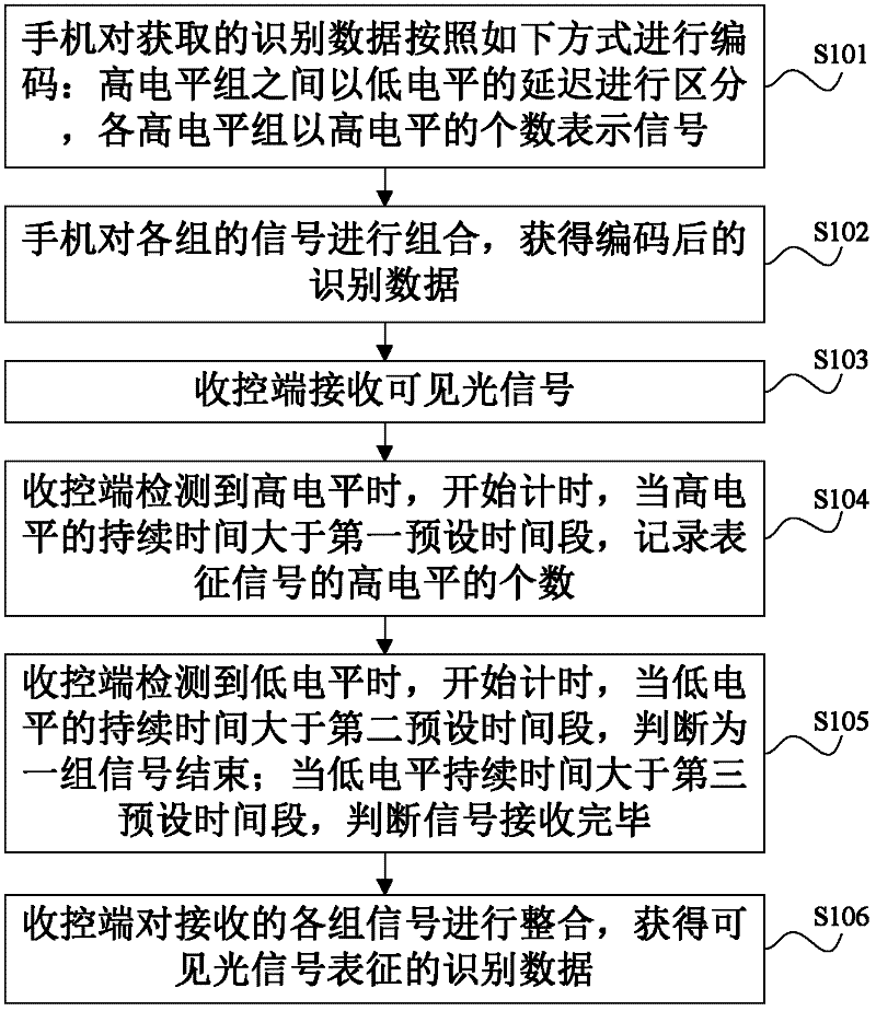
[0015] see figure 1 , is a flowchart of an encoding and decoding method based on communication of an access control system provided in Embodiment 1 of the present invention, and the encoding method includes:

[0016] S101: The mobile phone encodes the acquired identification data in the following manner: high-level groups are distinguished by low-level delays, and each high-level group represents a signal by the number of high levels.

[0017] Among them, the mobile phone is used as the sending end of the access control system.

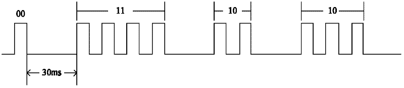
[0018] For example, the duration of each high level is 2ms, each group has a maximum of four high levels, each group of levels represents a 2bit signal, and four groups of signals represent a byte. That is: when the number of high levels in a group of signals is 1, it represents 00; when the number of high levels is 2, it represents signal 01; when the number of high levels is 3, it represents signal 10; when the number of high levels is 3, it repres...

Embodiment 2

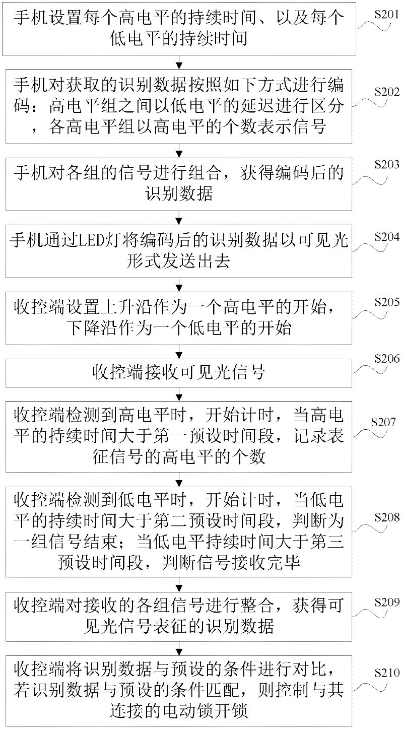
[0030] see image 3 , is a flow chart of an encoding and decoding method based on communication of an access control system provided in Embodiment 2 of the present invention, and the method includes:

[0031] S201: The mobile phone sets the duration of each high level and the duration of each low level. For example, set the duration of each high level to be 2ms, and the duration of each low level to be 30ms.

[0032] Among them, the mobile phone is used as the sending end of the access control system.

[0033] S202: The mobile phone encodes the acquired identification data in the following manner: high-level groups are distinguished by low-level delays, and each high-level group represents a signal by the number of high levels.

[0034] For example, the duration of each high level is 2ms, each group has a maximum of four high levels, each group of levels represents a 2bit signal, and four groups of signals represent a byte. That is: when the number of high levels in a group...


PUM


Abstract

The invention discloses a coding-decoding method based on communication of an access control system. The method comprises the steps of encoding the obtained identification data by a mobile phone according to the following modes: differentiating high level groups by delay of low level, wherein each high level group represents signal by quantity of high level; combining signals of each group to obtain the coded identification data; detecting the signal of visual light by a control terminal; beginning to time when detecting the high level; when the continuing time of the high level is longer than a first preset span, recording the quantity of the high level representing signal; beginning to time when detecting the low level; when the continuing time of the low level is longer than a second preset span, judging ending of a group of signals; when the continuing time of the low level is longer than a third preset span, judging finishing receiving signals; and combining the received different groups of signals so as to obtain the identification data representing visible light. Therefore, the communication based on the visible light between the mobile phone and the receiving and control terminal of the access control system is realized.

Description

technical field [0001] The invention relates to the technical field of access control system communication, in particular to an encoding and decoding method based on access control system communication. Background technique [0002] Wireless optical communication technology, also known as visible light communication, communicates through high-frequency flickering of LED light sources. Light represents 1, and no light represents 0. Its transmission rate is as high as gigabits per second. Wireless optical communication transmits data through visible light. Compared with microwave technology, it has quite abundant spectrum resources, which is unmatched by general microwave communication and wireless communication. At the same time, visible light communication can be applied to any communication protocol and any environment; In terms of reliability, there is no need to worry about the content of communication being stolen; the equipment of wireless optical communication is flexi...

Claims


Application Information

Patent Timeline
Patent Type & Authority Applications(China)
IPC IPC(8): G07C9/00
Inventor 刘若鹏栾琳李春来许学君
Owner KUANG CHI INTELLIGENT PHOTONIC TECH
Why Eureka
Try Eureka