Combustion burner for gas turbine

A gas turbine and combustion head technology, applied in the direction of burners, combustion chambers, combustion methods, etc., can solve problems such as uneven fuel injection, and achieve the effect of low NOx

Active Publication Date: 2012-09-26
MITSUBISHI POWER LTD
View PDF5 Cites 10 Cited by
  • Summary
  • Abstract
  • Description
  • Claims
  • Application Information

AI Technical Summary

Problems solved by technology

[0006] However, in the structure disclosed in the above-mentioned Patent Document 1, there is a problem that the gaseous fuel flow path (chamber) provided inside the swirler (rotating blade) 14 from the gaseous fuel flow path (fuel flow path) 8 16 fuel forms a vortex in the gas fuel flow path 16, and a pressure gradient is generated in the gas fuel flow path 16 due to the vortex, and the fuel injection amount from the small hole (injection hole) 15 becomes uneven.

Method used


Image

  • Combustion burner for gas turbine
  • Combustion burner for gas turbine
  • Combustion burner for gas turbine

Examples


Embodiment Construction

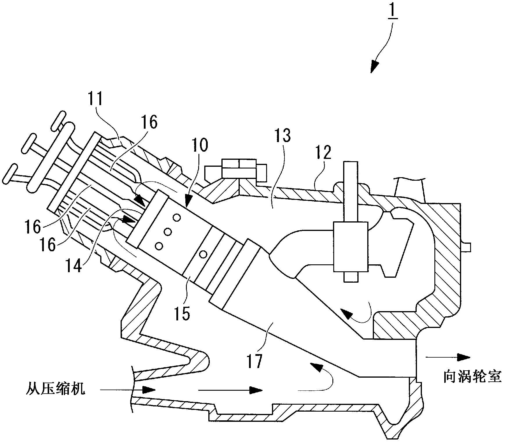
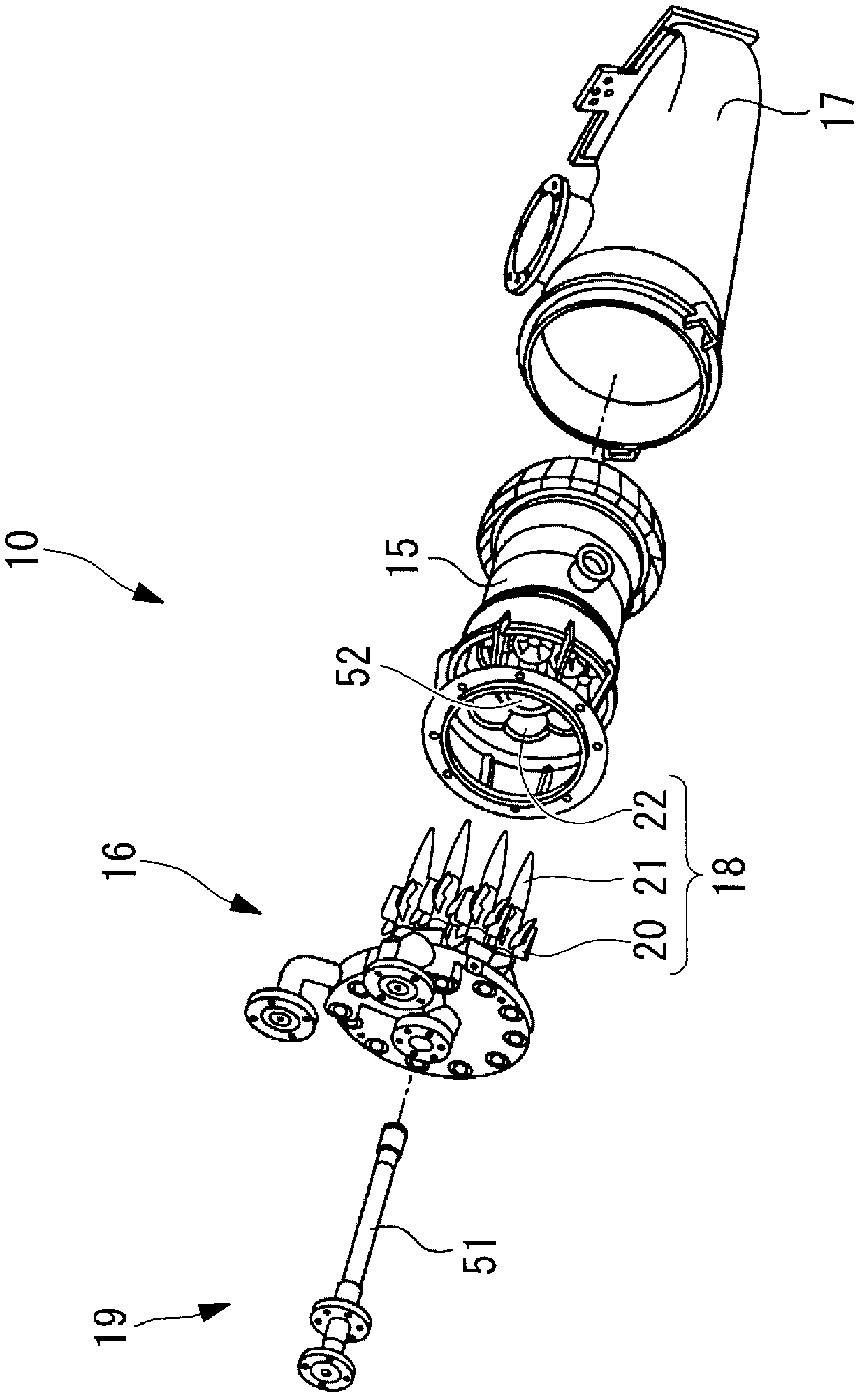
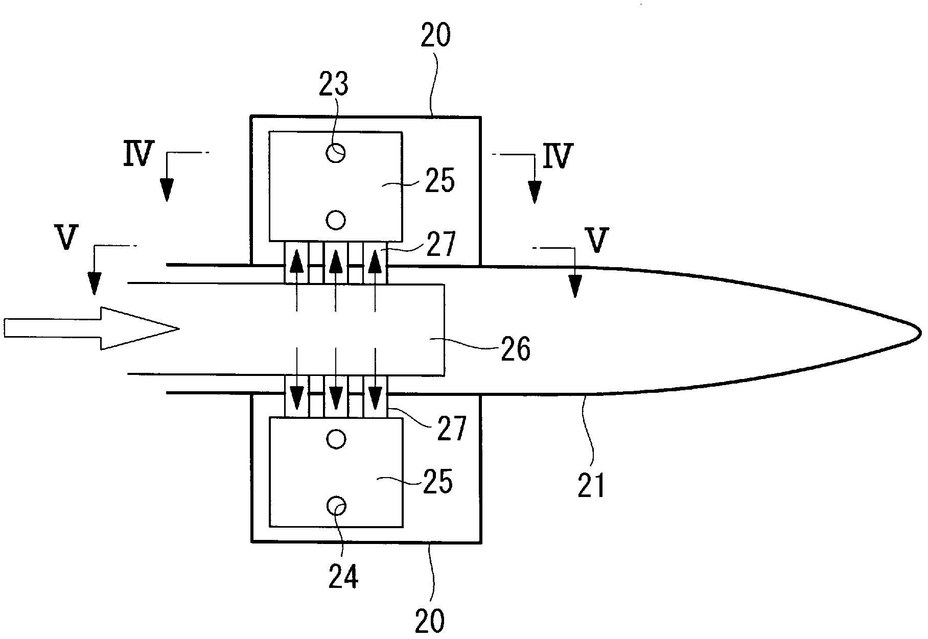
[0034] Below, refer to Figure 1 to Figure 5 A combustion head for a gas turbine according to a first embodiment of the present invention will be described. figure 1 is a schematic configuration diagram showing a gas turbine combustor provided with a combustion head for a gas turbine according to the present invention, figure 2 yes means figure 1 The diagram of the gas turbine combustor shown is an exploded perspective view of the fuel nozzle, inner tube and transition tube, image 3 It is an enlarged cross-sectional view showing a main part of the combustion head for a gas turbine according to the present embodiment, Figure 4 yes image 3 Sectional view of IV-IV direction, Figure 5 yes image 3 V-V cross-sectional view.

[0035] have figure 1 and figure 2 Gas turbine 1 (refer to figure 1 ) includes a compressor (not shown) and a turbine (not shown) in addition to the combustor 10 . A gas turbine often has a plurality of combustors 10 , mixes air (compressed air)...


PUM


Abstract

A combustion burner for a gas turbine, configured so that fuel is uniformly ejected from ejection holes to reduce the NOx generation of the gas turbine combustor. A combustion burner for a gas turbine, provided with: rotating vanes (20) for ejecting fuel from fuel ejection holes (23, 24) to air or a mixture gas of air and fuel, which flows from the upstream side, and applying a swirling force to the air or the mixture gas to create a swirling mixture gas flow; and a nozzle (21) which have the rotating vanes (20) disposed in a radiating manner on the outer peripheral surface thereof and which have formed therein a first fuel flow path (26) for guiding the fuel to the fuel ejection holes (23, 24). The rotating vanes (20) have provided therein cavities (25) which communicate with the fuel ejection holes (23, 24), and at least two second fuel flow paths (27) are provided between each cavity (25) and the first fuel flow path (26) so as to extend in the axial direction.

Description

technical field [0001] The present invention relates to a combustion head for a gas turbine provided with rotating blades (swirler blades) that inject fuel from a fuel injection hole to air or a mixture of air and fuel flowing from an upstream side, and impart rotational force to A swirling mixed air flow is formed. Background technique [0002] As such a combustion head for a gas turbine, for example, a configuration disclosed in Patent Document 1 is known. [0003] 【Prior technical literature】 [0004] 【Patent Literature】 [0005] [Patent Document 1] Japanese Patent Laid-Open No. 2003-74855 Contents of the invention [0006] However, in the structure disclosed in the above-mentioned Patent Document 1, there is a problem that the gaseous fuel flow path (chamber) provided inside the swirler (rotating blade) 14 from the gaseous fuel flow path (fuel flow path) 8 The fuel at 16 forms a vortex in the gas fuel flow path 16 , and a pressure gradient is generated in the gas f...

Claims


Application Information

Patent Timeline
Patent Type & Authority Applications(China)
IPC IPC(8): F23R3/14F02C7/22F23R3/28
CPCF23R3/286F23D2900/00008F23R3/36F23D2900/14004F23R3/14F23C2900/07001F23D2900/14701F23D2900/00003F02C7/22F23R3/28
Inventor 泷口智志赤松真儿佐藤贤治安部直树
Owner MITSUBISHI POWER LTD
Why Eureka
Try Eureka