Divided flow type master transmission reduction gear box of hot rolling mill

A reduction gear box and hot rolling mill technology, applied to the driving device for metal rolling mills, metal rolling, metal rolling, etc., can solve the problems of large space and unsatisfactory motor speed, so as to reduce production costs and improve Remote control ability, good stability effect

Active Publication Date: 2012-10-03
NANJING HIGH SPEED & ACCURATE GEAR GRP
View PDF5 Cites 1 Cited by
  • Summary
  • Abstract
  • Description
  • Claims
  • Application Information

AI Technical Summary

Problems solved by technology

[0004] The purpose of the present invention is to provide a new shunt type hot rolling mill for the practical problems that the space occupied by the current large-scale non

Method used


Image

  • Divided flow type master transmission reduction gear box of hot rolling mill
  • Divided flow type master transmission reduction gear box of hot rolling mill
  • Divided flow type master transmission reduction gear box of hot rolling mill

Examples


Embodiment Construction

[0022] The accompanying drawings disclose the specific structures of the embodiments of the present invention without limitation, and the embodiments of the present invention will be further described below in conjunction with the accompanying drawings.

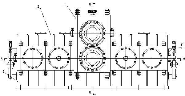
[0023] Depend on figure 1 It can be seen that the box body of this embodiment includes an upper box body 1 , a middle box body 2 and a lower box body 3 , and they are sequentially connected by bolts.

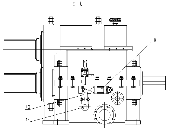
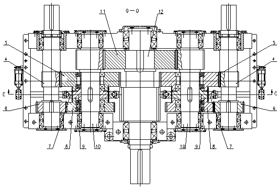
[0024] combined by graph image 3 Figure 4 It can be seen that the output shafts are the long output gear shaft 12 and the short output gear shaft 17, the two independent transmission systems with the same structure and parameters are symmetrically located on both sides of the long output gear shaft 12, the long output gear shaft 12, the short output gear shaft 17 and the independent The shafts in the transmission system are parallel to each other; wherein, the short output gear shaft 17 is supported on the junction of the u...


PUM


Abstract

The invention relates to a divided flow type master transmission reduction gear box of a hot rolling mill. The box bodies of the reduction gear box comprise an upper box body, a middle box body and a lower box body; the output shafts of the reduction gear box comprise a long output gear shaft and a short output gear shaft; two independent drive systems with the same structures and parameters are symmetrically located on the two sides of the long output gear shaft; the short output gear shaft is supported between the upper box body and the middle box body through a bearing; the long output gear shaft and shafts in the independent drive system are supported between the middle box body and the lower box body through the bearing; the independent drive system comprises an input gear shaft and a middle gear shaft; a high and low speed gearshift mechanism is arranged on the middle gear shaft; a high and low speed shift gear in the high and low speed gearshift mechanism is engaged with a high and low speed gear in the input gear shaft; an output gear is mounted on the long output gear shaft through a key; a gear on the middle gear shaft is engaged with the output gear on the long output gear shaft; the gears on the long output gear shaft and the short output gear shaft are mutually engaged; and the high and low speed gearshift mechanism is arranged on the middle gear shaft and is synchronously adjusted through a synchronous gearshift device.

Description

technical field [0001] The invention relates to a hot-rolling main drive reduction gearbox, in particular to a main drive reduction gearbox for a split flow hot rolling mill. Background technique [0002] The main drive reduction gearbox is one of the key equipment in the hot rolling equipment of non-ferrous metals. In the hot rolling field of non-ferrous metals, the hot rolling main drive reduction gearbox is generally driven by one motor at the same time. Two output shafts , this single-input and double-output working mode, for the high-power hot-rolled main drive reduction gearbox, not only needs to be equipped with a relatively high-power motor, but also each transmission gear, especially the input gear shaft needs to have a large mechanical strength. For this reason, the high-power hot-rolled main drive reduction gearbox is improved. The two outputs are separately driven by independent transmission systems, and the transmission mode of double input and double output is...

Claims


Application Information

Patent Timeline
IPC IPC(8): B21B35/12
Inventor 陈亮郑光薛美华吕海明
Owner NANJING HIGH SPEED & ACCURATE GEAR GRP
Why Eureka
Try Eureka