Cable cut-off tool

A technology for cutting knives and cables, which is applied to shearing devices, knives for shearing machine devices, metal processing equipment, etc., and can solve problems such as inconvenient use, unreasonable structure of cable cutting knives, and poor cutting effect. Achieve the effect of convenient operation, improved cutting effect and simple structure

Active Publication Date: 2012-10-03
CHENGDU QIPING TECH CO LTD
View PDF4 Cites 7 Cited by
  • Summary
  • Abstract
  • Description
  • Claims
  • Application Information

AI Technical Summary

Problems solved by technology

[0003] The purpose of the present invention is to provide a cable cutting knife, which solves the problems of poor cutting effect caused by unreasonable structure and inconvenient use of the current cable cutting knife

Method used


Image

  • Cable cut-off tool
  • Cable cut-off tool

Examples


Embodiment

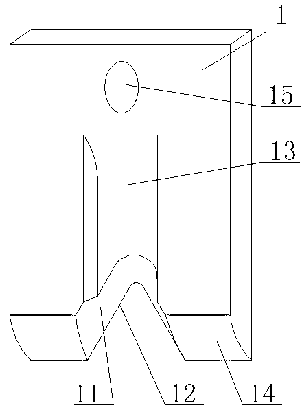
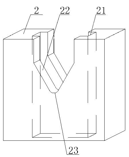
[0034] Such as figure 1 and figure 2 As shown, the cable cutting knife is mainly composed of a blade 1 and a combined knife seat 2 that cooperate with each other, wherein the blade 1 and the combined knife seat 2 are all made of hard alloy, which improves the service life of the present invention, and utilizes The unique structural design and high-precision matching relationship of the present invention have greatly improved the problem that the existing cable cutting tools do not cut cleanly on special cables such as cables with Kevlar protective layers, and there are a lot of fiber residues. In the manufacturing process of the present invention, the accuracy of the blade 1 and the combined tool holder 2 itself is controlled within 5 microns (ie 0.005 mm) by using special and precise techniques, and the matching accuracy of the two is controlled within 2 microns (ie 0.02 mm). within mm). The unique structural design of the present invention is described in detail below.

...


PUM


Abstract

The invention discloses a cable cut-off tool, and belongs to a mechanical technology. The cable cut-off tool mainly comprises a blade and a combined tool seat which are matched with each other, wherein an inverted V-shaped blade cutting edge angle is formed at the lower end of the blade; a blade cutting edge is formed on the blade cutting edge angle; a blade sliding chute matched with the blade is formed on the combined tool seat; a cable withdraw slot and a groove are formed on the blade; and a tool seat cutting edge angle and a supporting base are arranged on the combined tool seat. The cable cut-off tool is ingenious in design, simple in structure, small in size and convenient to operate; due to the unique structural design, the cutting effect is greatly enhanced; clean and flat cutting is guaranteed when a cable or particularly a special cable is cut, so that cutting residues are avoided; moreover, cutting energy consumption is greatly reduced; and meanwhile, the service life is greatly prolonged.

Description

technical field [0001] The invention relates to a cutting knife, in particular to a cable cutting knife. Background technique [0002] The structure of any cable can be divided into three parts, namely conductor, insulation shielding layer and protective layer. With the development of various technologies, although the overall structure of the three parts has not changed much, the specific structure and materials of each part have undergone tremendous changes. Especially for some cables used in special environments, most of the protective layers are made of high-performance materials. In the application of cables, it is often necessary to cut the cables in a limited environment, and the special protective layer cables with high-performance materials usually require a large operating environment when cutting, such as cutting with Kai Cables with a protective sheath. The currently used cable cutting tool has an unreasonable structure and is inconvenient to use, especially w...

Claims


Application Information

Patent Timeline
Patent Type & Authority Applications(China)
IPC IPC(8): B23D35/00
Inventor 付强
Owner CHENGDU QIPING TECH CO LTD
Why Eureka
Try Eureka