Precision numerical control rotary workbench

A technology of rotary table and table, applied in the direction of manufacturing tools, metal processing equipment, metal processing machinery parts, etc., can solve the problems of transmission clearance, affecting transmission accuracy, affecting positioning accuracy, etc., and achieves improved accuracy and large transmission torque. , the effect of saving electricity

Inactive Publication Date: 2012-10-03
TIANJIN NO 1 MACHINE TOOL WORKS
View PDF4 Cites 10 Cited by
  • Summary
  • Abstract
  • Description
  • Claims
  • Application Information

AI Technical Summary

Problems solved by technology

Practice has proved that worm gear transmission and gear transmission can provide high transmission accuracy and high transmission stability, but affected by various uncertain factors such as machining, assembly and debugging, the worm gear transmission of CNC rotary table There is inevitably a transmission gap in the process, which in turn affects the transmission accuracy
[0005] Most CNC rotary table bases support the rotary spindle by static pressure support, YRT three-row cylindrical roller bearing support, or ordinary friction support with special materials as contact materials; although static pressure support has better support rigidity , but under the action of eccentric load force, especially the impact force of eccentric load, the end runout accuracy of the table top is poor; the positioning accuracy of YRT three-row cylindrical roller bearing is constant; Very limited in terms of stability
[0006] The workbench in most workplaces does not need to rotate continuously, but rotates intermittently according to the working conditions. When the working conditions need to be stopped, the motor needs to be in the enabled state all the time, otherwise the positioning accuracy will be affected.

Method used


Image

  • Precision numerical control rotary workbench
  • Precision numerical control rotary workbench
  • Precision numerical control rotary workbench

Examples


Embodiment Construction

[0014] In order to further understand the invention content, characteristics and effects of the present invention, the following examples are given, and detailed descriptions are as follows in conjunction with the accompanying drawings:

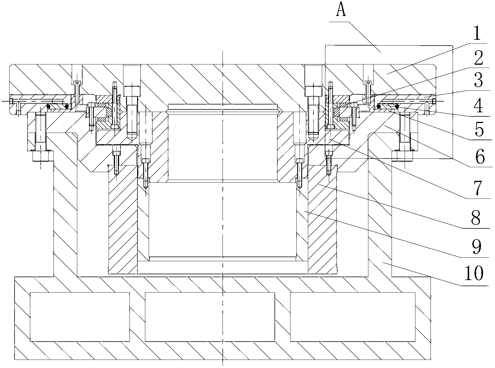
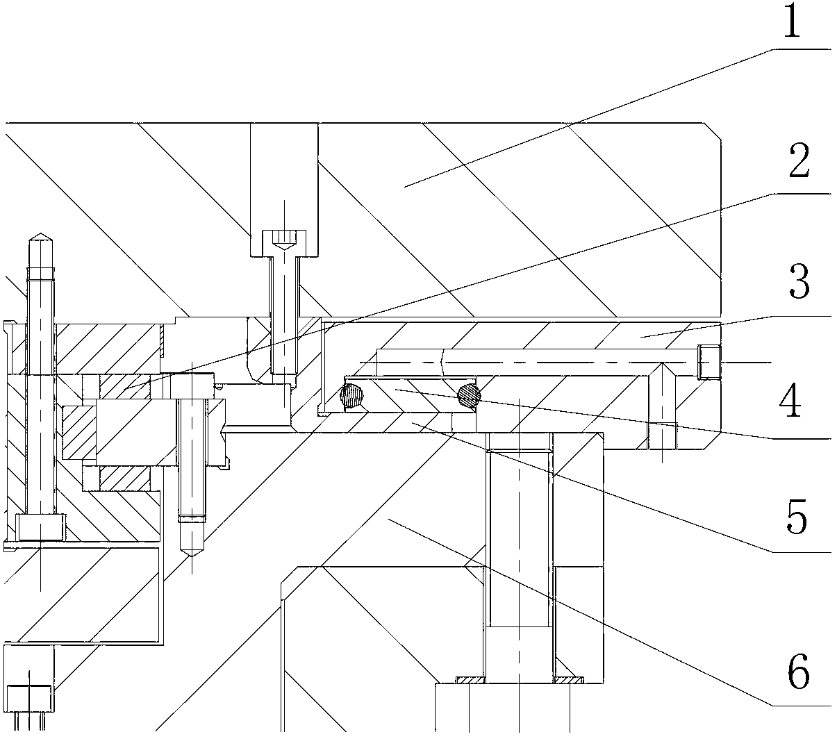
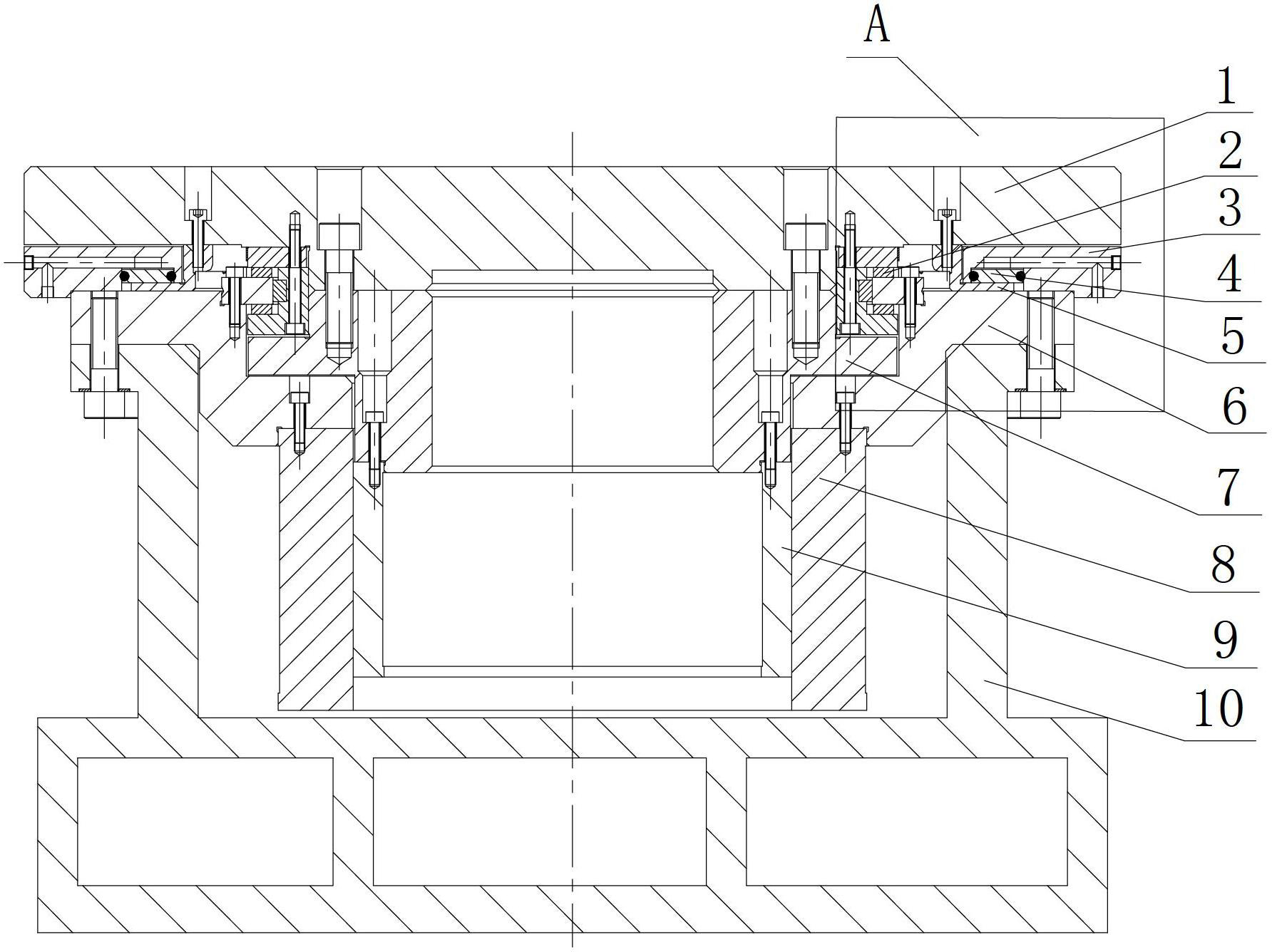
[0015] see figure 1 with figure 2 , a precision numerical control rotary workbench, including a workbench base 10, a workbench spindle 1, and a spindle mandrel 7 fixedly connected to the workbench spindle. A support sleeve 6 is fixedly connected to the base 1 of the workbench, and the outer ring of the turntable bearing 2 and the hydraulic clamping cylinder 3 are installed on the support sleeve, and the torque motor stator 8 is fixedly connected to the bottom of the support sleeve 6 . The workbench main shaft 1 is installed on the inner ring of the turntable bearing 2, and the torque motor rotor 9 is connected under the main shaft mandrel 7, and the hydraulic clamping cylinder spring pressing plate 5 is installed under the workbench main sh...


PUM


Abstract

The invention relates to a precision numerical control rotary workbench which comprises a workbench base, a workbench spindle and a spindle mandrel fixedly connected with the workbench spindle, wherein a support sleeve is fixedly connected on the workbench base, a rotary workbench bearing outer race and a hydraulic clamping cylinder are installed on the support sleeve, a torque motor stator is fixedly connected on the bottom of the support sleeve, the workbench spindle is installed on the inner race of the rotary workbench bearing, a torque motor rotor is connected below the spindle mandrel, a hydraulic clamping cylinder spring compaction sheet is installed below the workbench spindle, a hydraulic clamping cylinder piston is assembled in a groove of the hydraulic clamping cylinder, and the hydraulic clamping cylinder piston is in contact with the hydraulic clamping cylinder spring compaction sheet. The precision numerical control rotary workbench has the advantages of increasing the bench surface precision and the positioning precision of the workbench under the action of unbalance load impact force, the transmission torque is large, and the assembly is simple and reliable; and the precision numerical control rotary workbench has self-locking function, so that the torque motor can work discontinuously, and the electric energy is saved.

Description

technical field [0001] The invention belongs to the field of machine tool manufacturing, in particular to a precision numerical control rotary worktable. Background technique [0002] The CNC rotary table is the core component of various machine tools such as vertical lathes, milling machines, machining centers, and CNC gear shaping machines. Production processing capacity and efficiency. The current application status of CNC rotary table is not ideal. [0003] At present, the drive mode of CNC rotary table is mainly servo motor or torque motor. Servo motor is suitable for high-speed occasions, and torque motor is suitable for low-speed and high-torque occasions. Precision CNC rotary table generally requires a lower speed. [0004] The transmission mode of the CNC rotary table includes worm gear transmission and gear transmission. Practice has proved that worm gear transmission and gear transmission can provide high transmission accuracy and high transmission stability, b...

Claims


Application Information

Patent Timeline
Patent Type & Authority Applications(China)
IPC IPC(8): B23Q1/26
Inventor 刘福聪王秀梅
Owner TIANJIN NO 1 MACHINE TOOL WORKS
Why Eureka
Try Eureka