Continuous sanding machine for sheet metal surface

A sand mill and metal plate technology, which is applied to metal processing equipment, machine tools suitable for grinding workpiece planes, grinding machines, etc., can solve the problems of reducing work efficiency, increasing repeated investment in equipment, and complicated adjustments, so as to improve production Efficiency, the effect of realizing continuous processing and production

Inactive Publication Date: 2016-05-11
临安华创机械设备有限公司
View PDF5 Cites 0 Cited by
  • Summary
  • Abstract
  • Description
  • Claims
  • Application Information

AI Technical Summary

Problems solved by technology

However, the existing metal plate surface sand mills on the market have the following disadvantages: first, they cannot realize multi-functional integration, and need two production lines for sanding and chaotic lines, which not only increases the repeated investment in equipment, but also reduces the work cost. Efficiency; Second, the existing sand mills can only process single sheets of aluminum foil and other metal plates, and cannot achieve continuous processing operations. The adjustment in the operation is complicated, which increases the workload
[0003] It can be seen from the above that in order to realize the multi-purpose of the existing metal plate sand mill, combine multiple production lines into one equipment, overcome the existing disadvantages of only being able to process single metal plates, and realize continuous processing and production, it is necessary improve it

Method used


Image

  • Continuous sanding machine for sheet metal surface
  • Continuous sanding machine for sheet metal surface

Examples


Embodiment Construction

[0029] The present invention will be further described below with reference to the drawings and embodiments.

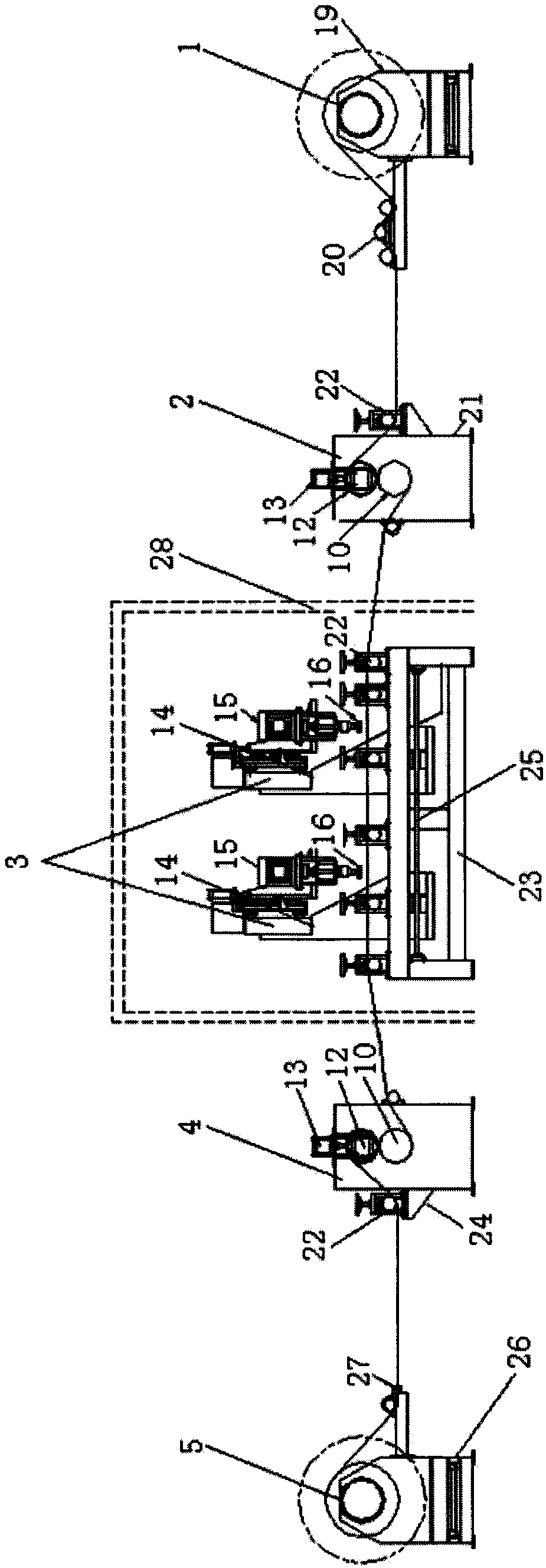
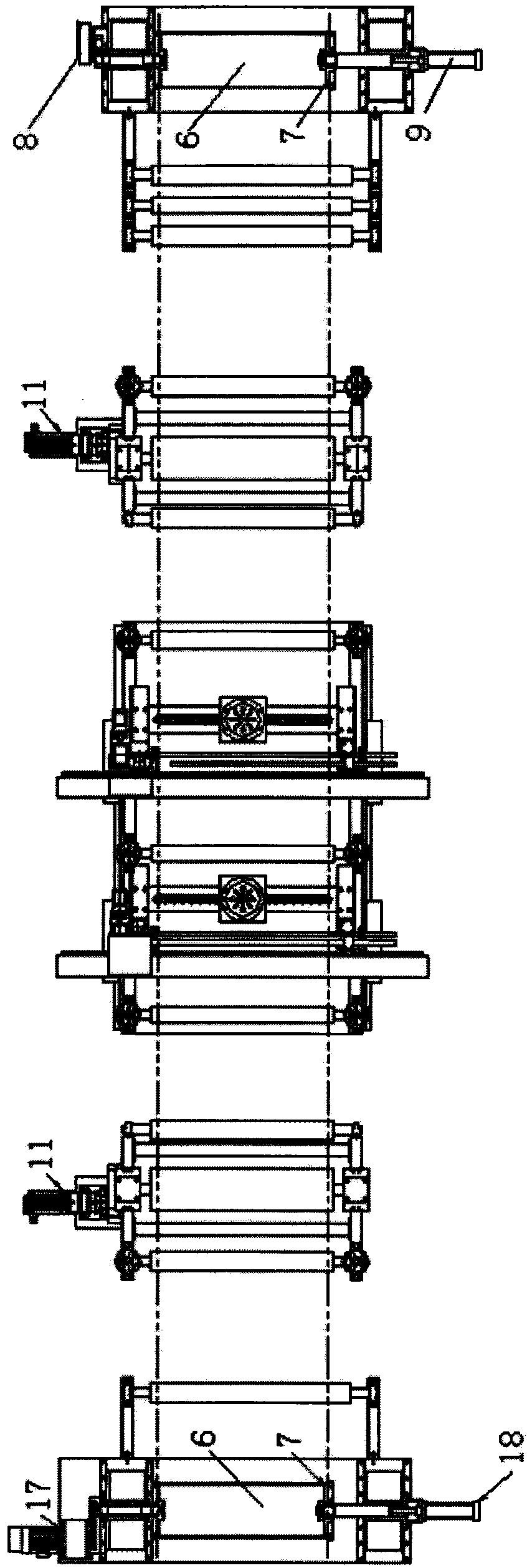
[0030] figure 1 It is a schematic diagram of the structure of the continuous sand mill for the metal plate surface provided by the present invention; figure 2 It is a schematic diagram of the structure of a continuous sand mill for a metal plate surface provided by the present invention.

[0031] See figure 1 with figure 2 , The metal plate surface continuous sand mill provided by the present invention is provided with an unwinding device 1, an unwinding traction device 2, a sanding device 3, a winding traction device 4, and a winding device 5 in sequence, wherein the unwinding device 1 includes a core tube 6, two top heads 7, an unwinding brake 8 and an unwinding head cylinder 9. The top heads 7 are located at both ends of the core tube 6, and one of the top heads 7 is provided with an unwinding brake 8 , The other top head 7 is provided with an unwinding head cylinde...


PUM


Abstract

The invention discloses a continuous sanding machine for metal plate surfaces. An unreeling device, an unreeling traction device, a sanding device, a reeling traction device and a reeling device are sequentially provided, wherein the unreeling device comprises a core barrel, two jacking parts, an unreeling brake and an unreeling jacking cylinder; the unreeling traction device comprises a traction roller and a traction motor; the sanding device comprises two groups of sanding parts, each group of sanding parts comprise a sanding machine and a motor driving the sanding machine to rotate, and a mold is installed at the lower side of the motor; the reeling traction device comprises a traction roller and a traction motor; and the reeling device comprises a core barrel, two jacking parts, a reeling motor and a reeling jacking cylinder. The continuous sanding machine for metal plate surfaces provided by the invention has multiple purposes, multiple production lines are merged into one facility, the defect that only one metal board can be machined by using the traditional machine is overcome, continuous machining and production is realized, and the production efficiency is increased.

Description

Technical field [0001] The invention relates to a device for dry grinding a pattern on the surface of a metal plate, in particular to a continuous sand mill for the surface of a metal plate. Background technique [0002] Metal plate surface sander is a kind of equipment for dry grinding of various patterns on aluminum foil and other metal surfaces. It produces a wide variety of products and is widely used in indoor and outdoor decoration, such as aluminum-plastic panels, ceilings, cabinets, aluminum buckles Board etc. However, the existing metal plate surface sanding machine on the market has the following shortcomings: First, it cannot realize multifunctional integration, and two production lines of sanding and chaotic patterns are required, which not only increases the repeated investment of equipment, but also reduces the work. Efficiency: Second, the existing sand mill can only process a single sheet of aluminum foil and other metal plates, and cannot achieve continuous proc...

Claims


Application Information

Patent Timeline
Patent Type & Authority Patents(China)
IPC IPC(8): B24B27/00B24B7/10
Inventor 华洪潮
Owner 临安华创机械设备有限公司
Why Eureka
Try Eureka