Driving device for electric lumbar system

A driving device and lumbar support technology, applied in the direction of the back cushion, etc., can solve the problems of short service life, large outer diameter, insufficient rigidity, etc., and achieve the effect of long service life, good stability and improved rigidity

Inactive Publication Date: 2012-10-03
东莞市凌锐汽车零部件有限公司 +1
View PDF5 Cites 4 Cited by
  • Summary
  • Abstract
  • Description
  • Claims
  • Application Information

AI Technical Summary

Problems solved by technology

[0005] The object of the present invention is to provide an electric lumbar support system drive device for the deficiencies of the prior art, which solves the problems existing in the existing electric adjustment drive: larger outer diameter, more teeth, bulky Defects such as large size, insufficient rigidity, short service life, and insufficient stability

Method used


Image

  • Driving device for electric lumbar system
  • Driving device for electric lumbar system
  • Driving device for electric lumbar system

Examples


Embodiment Construction

[0039] The present invention will be further described below in conjunction with the accompanying drawings.

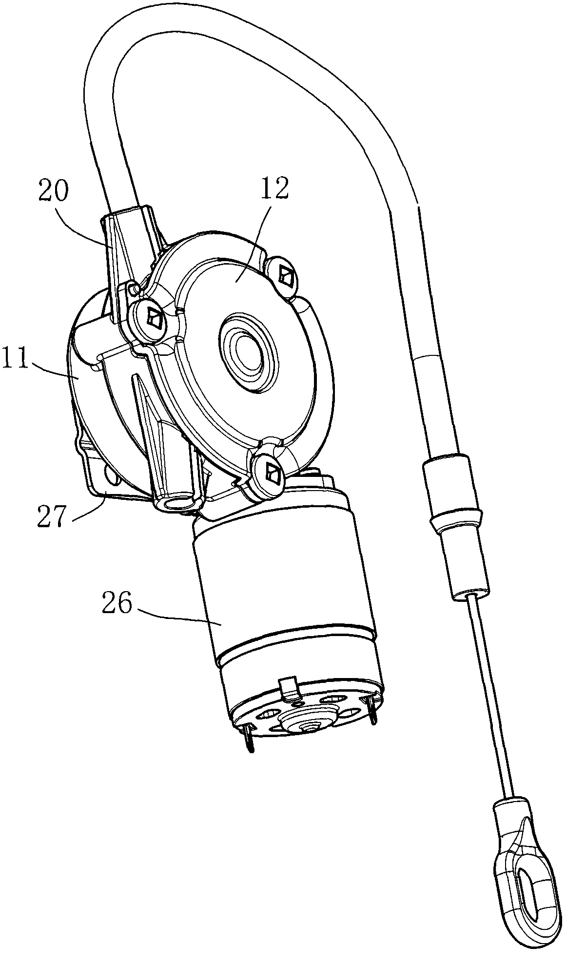
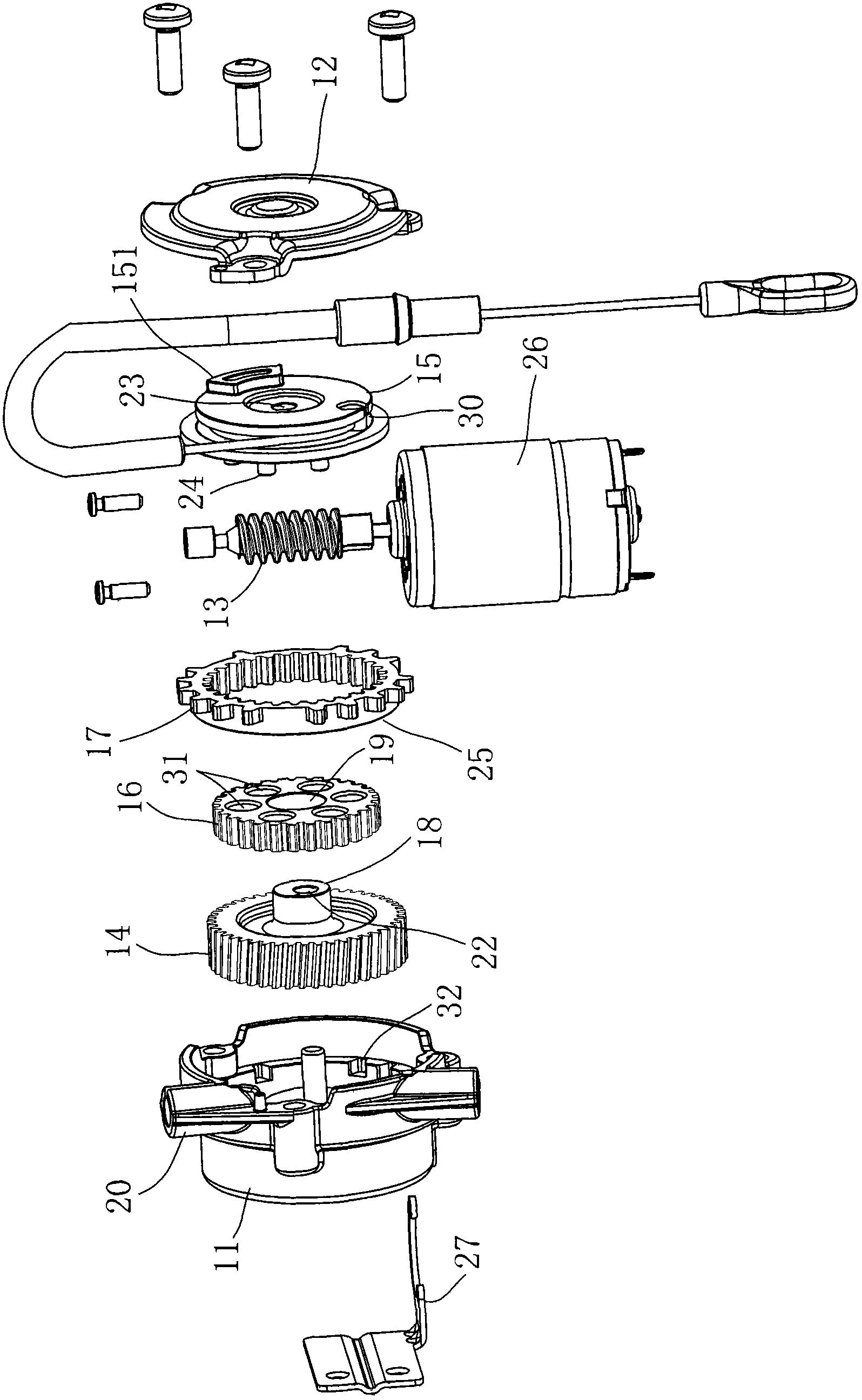
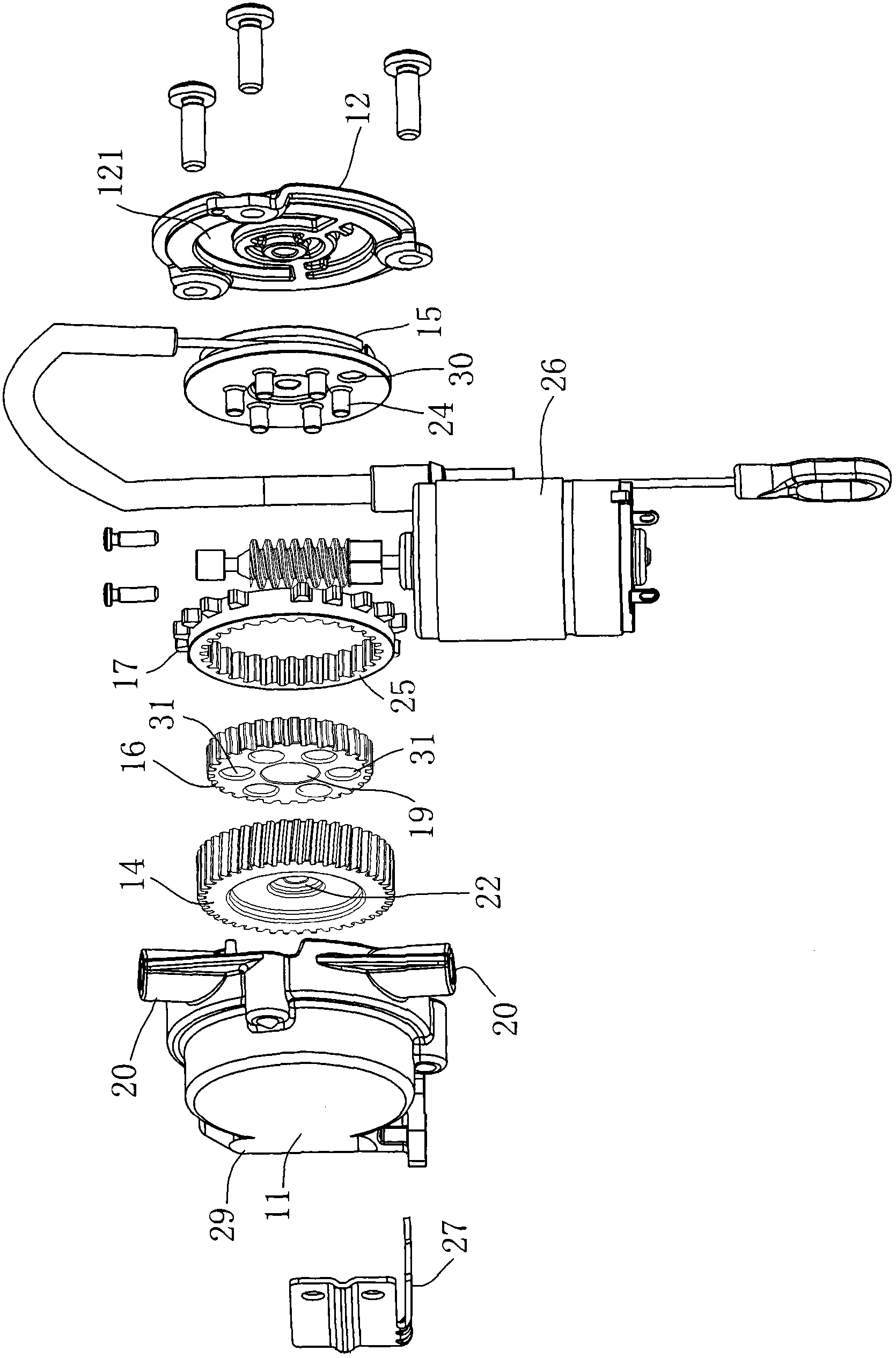
[0040] Such as figure 1 —— image 3 , is the first embodiment of the driving device of the electric lumbar support system of the present invention, including a box body 11, an upper cover 12, a worm screw 13, a worm wheel 14, a wire wheel 15, and an eccentric wheel 16, and the box body 11 and the upper cover 12 are locked together by screws. Together they form a box body. There is a worm wheel 14 in the box body 11. The worm wheel 14 cooperates with the worm screw 13. The worm screw 13 is driven by the motor 26 to rotate. The worm screw 13 drives the worm wheel 14 to rotate. 16 produces eccentric motion, and the eccentric wheel 16 drives the wire wheel 15, and the wire wheel 15 is fixed with a drag cable;

[0041] The present invention drives the worm screw 13 to rotate rapidly through the motor 26, drives the worm wheel 14 to rotate slowly, then axially drives the e...


PUM


Abstract

The invention relates to the technical field of a reeling-unreeling device and particularly relates to a driving device for an electric lumbar system. The driving device comprises a box body, an upper cover, a worm, a worm gear, a wire wheel and an eccentric wheel, wherein the box body and the upper cover are assembled to form a case body; the case body is provided with a wire outlet groove; the box body is internally provided with the worm gear; the worm gear is matched with the worm; the eccentric wheel doing eccentric movement is axially driven by the worm gear; and the wire wheel is axially driven by the eccentric wheel. A scheme that the eccentric wheel doing eccentric movement is driven by the worm gear and the wire wheel is driven by the eccentric wheel is adopted, the outer diameter of the worm gear can be greatly lessened, the quantity of teeth outside the worm gear is remarkably reduced, the difference between the quantity of teeth of the eccentric wheel and the quantity of teeth of the wire wheel is small, the whole size is small, and the rigidity of the worm gear is improved; and cascade type multi-step transmission is adopted, a high transmission ratio is achieved, the whole stability is good and the service life is long.

Description

technical field [0001] The invention relates to the technical field of wire take-up and release devices, in particular to an electric lumbar support system driving device. Background technique [0002] The car seat backrest adjustment system uses the cable to pull the backrest device to produce the effect of waist adjustment, including manual adjustment and electric adjustment. Among them, the working principle of the electric adjustment driver is to drive the worm gear through the high-speed motor At the same time, the worm gear is equipped with one or more planetary gear trains, and the planetary gear train is assembled on the wire wheel, and the wire wheel drives the cable to realize the deceleration between the motor and the cable to adjust the car seat. Backrest device. [0003] The main disadvantages of the above-mentioned existing electric adjustment driver are that since the motor drives the worm to rotate at a relatively high speed, in order to enable the wire whee...

Claims


Application Information

Patent Timeline
Patent Type & Authority Applications(China)
IPC IPC(8): B60N2/66
Inventor 舒易久刘金涛
Owner 东莞市凌锐汽车零部件有限公司
Why Eureka
Try Eureka