Body type epistemic passive biped walking robot system
A walking robot and robot system technology, applied in the field of quasi-passive walking robots, can solve the problems of not conforming to the natural gait, poor system reliability, complex control, etc., to save installation space, low walking energy consumption, and low energy consumption. Effect
- Summary
- Abstract
- Description
- Claims
- Application Information
AI Technical Summary
Problems solved by technology
Method used
Image
Examples
specific Embodiment approach 1
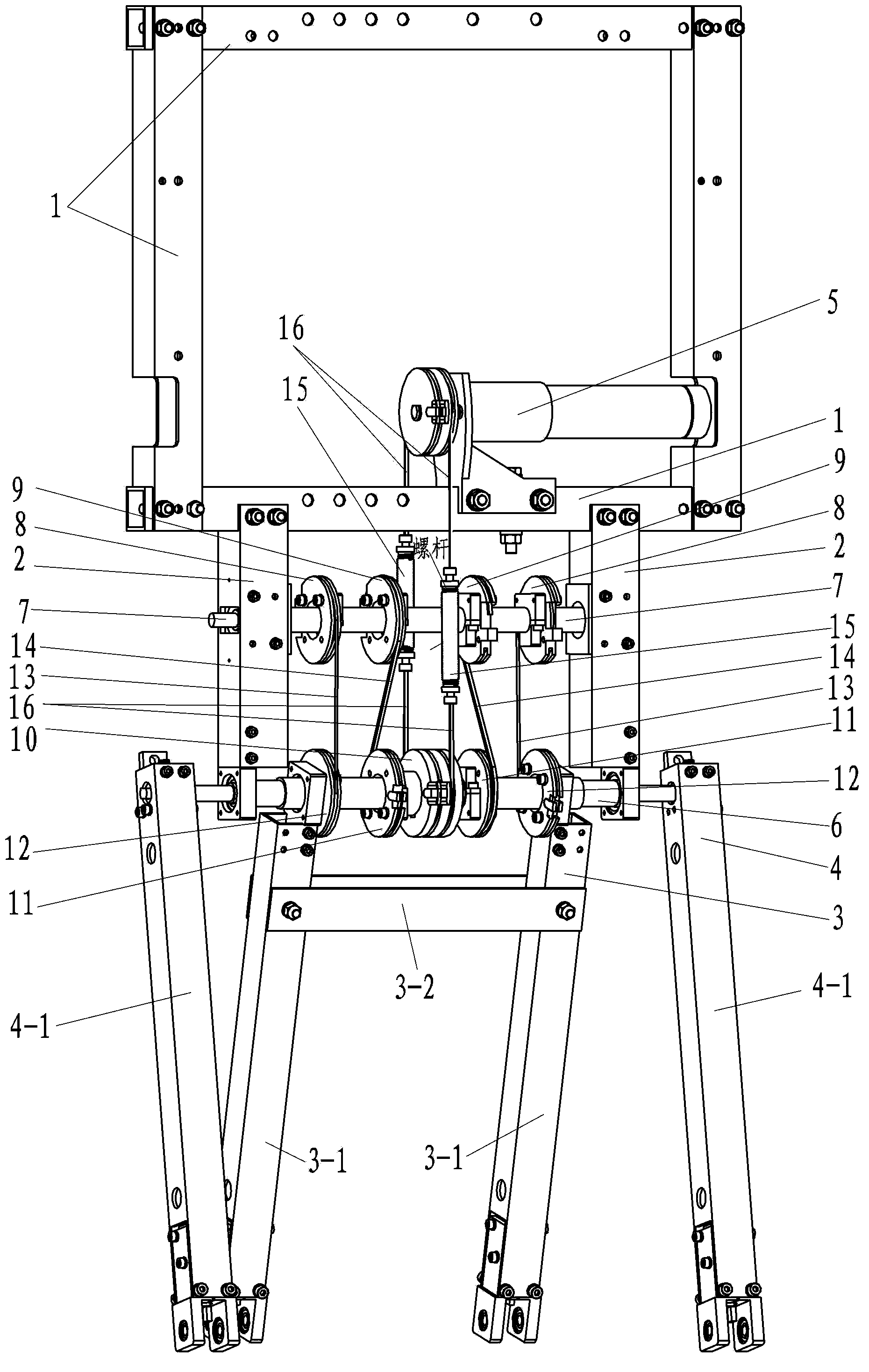
[0021] Specific implementation mode one: as Figure 1~4 As shown, 1. a body-type quasi-passive biped walking robot system described in this embodiment, the robot system includes a body, inner legs 3 and outer legs 4 and a motor 5, and the body includes an upper frame 1 and two The column 2, the lower frame of the upper frame 1 is connected to the upper ends of the two columns 2, the motor 5 is installed on the upper frame 1, and it is characterized in that: the robot system also includes a main shaft 6, an auxiliary shaft 7, and two first auxiliary wheels 8. Two second auxiliary wheels 9, motor drive wheel 10, two outer leg drive wheels 11, two inner leg drive wheels 12, two first steel wire ropes 13, two second steel wire ropes 14, two series elastic drives Unit 15 and four third steel wire ropes 16; inner leg 3 is made of cross brace 3-2 and two single inner legs 3-1, and cross brace 3-2 connects the thighs of two single inner legs 3-1 together, The outer leg 4 is composed ...
specific Embodiment approach 2
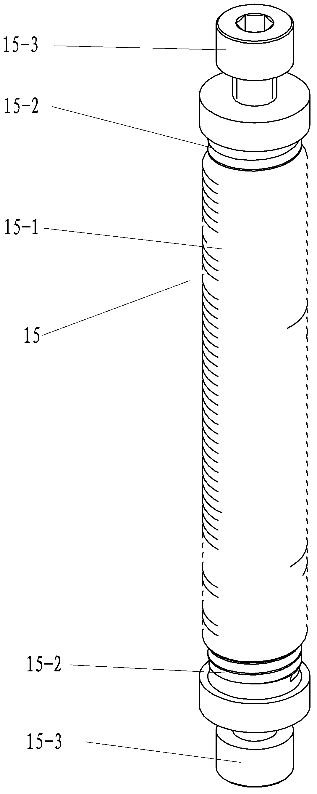
[0022] Specific implementation mode two: as Figure 1~4As shown, in this embodiment, each series elastic driving unit transmission mechanism 15 is composed of a spring 15-1, two screw rods 15-2 and two bolts 15-3, and the two ends of the spring 15-1 are connected with a screw rod 15 respectively. -2 threaded connection, the outer end of the screw rod 15-2 is screwed with a bolt 15-3; the bolts 15-3 at the upper and lower ends of the transmission mechanism 15 of each series elastic drive unit are respectively connected with one end of a third steel wire rope 16. The serial elastic drive unit with this structure can change the effective number of coils of the spring by adjusting the screw-in depth of the screw rod 15-2 in the spring 15-1, thereby adjusting the spring stiffness and then the stiffness of the entire serial elastic element. The utility model has the advantages of simple structure and easy adjustment. Other components and connections are the same as those in the fir...
specific Embodiment approach 3
[0023] Specific implementation mode three: as Figure 1~4 As shown, in the present embodiment, each single inner leg 3-1 and each single outer leg 4-1 all comprise upper leg 21, lower leg 22, electromagnet 23, electromagnet pin 24 and knee joint shaft 25, upper leg The lower end of 21 and the upper end of lower leg 22 are rotationally connected by knee joint shaft 25, the lower end of upper leg 21, the upper end of lower leg 22, knee joint shaft 25, electromagnet 23 and electromagnet pin 24 constitute a knee joint locking mechanism, and electromagnet 23 is installed At the lower end of the upper leg 21 , the upper end of the lower leg 22 is provided with a pin hole 26 for inserting the electromagnet pin 24 , and the lower end of the upper leg 21 is also provided with a positioning surface 27 . The positioning surface 27 can further limit the swing of the lower leg, enhancing positioning reliability. Other compositions and connections are the same as those in Embodiment 1 or 2...
PUM
 Abstract
Description
Claims
Application Information
 - R&D
- Intellectual Property
- Life Sciences
- Materials
- Tech Scout
- Unparalleled Data Quality
- Higher Quality Content
- 60% Fewer Hallucinations
Browse by: Latest US Patents, China's latest patents, Technical Efficacy Thesaurus, Application Domain, Technology Topic, Popular Technical Reports.
© 2025 PatSnap. All rights reserved.Legal|Privacy policy|Modern Slavery Act Transparency Statement|Sitemap|About US| Contact US: help@patsnap.com


