Volute energy storage pushing trolley with braking device

A technology with brakes and energy storage, which is applied in storage devices, transportation and packaging, etc., can solve the problems that the pushing trolley does not have a braking function, and the pushed items cannot be stopped at any time, and achieves simple structure, low failure rate, and easy manufacturing Effect

Active Publication Date: 2012-10-03
JIANGSU XUNJIE HARNESS TECH
View PDF9 Cites 2 Cited by
  • Summary
  • Abstract
  • Description
  • Claims
  • Application Information

AI Technical Summary

Problems solved by technology

However, the device still relies on the gravity of heavy objects to slide down, and the pushing effect needs to be further improved.
[0004] The Chinese patent "A Drawer-Type Boxed Item Storage and Distribution Device with Automatic Push Function" discloses a push trolley, but the push trolley does not have a braking function and cannot be stopped at any time during the process of pushing items

Method used


Image

  • Volute energy storage pushing trolley with braking device
  • Volute energy storage pushing trolley with braking device
  • Volute energy storage pushing trolley with braking device

Examples


Embodiment 1

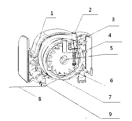
[0029] When pushing the boxed items, first fix the front end of the traction line on a fixed object, and pull the trolley backwards by hand. At this time, the worm coil disk rotates, the worm coil spring stores energy, and the boxed items are arranged neatly and placed on the bottom plate , then loosen the hand to release the trolley, the worm coil spring releases energy, the worm coil disk rotates in another direction and pulls the traction wire, the trolley will move forward and push the boxed items in front of it to move, and finally the boxed items will be out of the warehouse .

[0030] When you need to stop the trolley in an unexpected situation, you can press the brake button device at any time. At this time, the trolley is locked and cannot move; when the accident is eliminated, you can press the brake button device again, the trolley lock is released, the car continues to move.

[0031] The pushing device of the present invention can stop pushing at any time, and can...

Embodiment 2

[0033] When pushing bottled items, first fix the front end of the traction line on a fixed object, and pull the trolley backward by hand. At this time, the worm coil disk rotates, and the worm coil spring stores energy. The bottled items are arranged neatly and placed on the bottom plate, and then Release the hand to release the trolley, the worm coil spring releases energy, the worm coil disk rotates in another direction and pulls the traction wire, the trolley will move forward and push the bottled items in front of it to move, and finally the bottled items will be out of the warehouse.

[0034] When you need to stop the trolley in an unexpected situation, you can press the brake button device at any time. At this time, the trolley will be locked and the trolley cannot move; Release, the car continues to move.

[0035] The pushing device of the present invention can stop pushing at any time, can determine the parking position in batches according to the size of the items, an...


PUM


Abstract

The invention discloses a volute energy storage pushing trolley with a braking device. Rollers are arranged below a shell; a volute plate is arranged in the shell; a volute spring is arranged in the volute plate; a traction wire is wound on the periphery of the volute plate; the volute plate can be driven by elasticity of the volute spring to rotate; the side face of the volute plate is fixedly connected with a braking ratchet wheel; the braking ratchet wheel and the volute plate are coaxially arranged; the shell is also provided with a brake button device; one end of the brake button device is positioned in the shell, and the other end of the brake button device is positioned outside the shell; the brake button device in the shell is in contact with a brake disc; a return spring is sleeved on the brake disc; the other end of the return spring is fixedly connected to the shell; when the brake button device is pressed down, the brake disc is clamped on the teeth of the brake ratchet wheel; and when the brake button device is reset, the brake disc is separated from the teeth of the brake ratchet wheel. The volute energy storage pushing trolley with the braking device has the advantages of simple structure, convenience in manufacturing, low failure rate and suitability for large-scale application.

Description

technical field [0001] The invention relates to a pushing device, in particular to a scroll energy storage pushing trolley with a braking device. Background technique [0002] At present, most of the existing domestic and foreign equipment for automatically distributing items for storage, replenishment, and out of the warehouse are realized by unpowered, slope-type storage channels. This technical structure is relatively simple, but the main disadvantage is that the slope produces a large inclination angle. The space utilization rate is low, the amount of storage is small, and the replenishment speed is slow, which cannot meet the needs of a large number of replenishment and exit. Especially due to the use of slope storage, no power to push, all depends on the gravity of the items themselves to slide down to achieve the purpose of getting out of the warehouse. When the gravity of the items themselves cannot overcome the friction, the storage will stagnate in the storage chan...

Claims


Application Information

Patent Timeline
Patent Type & Authority Applications(China)
IPC IPC(8): B65G1/04
Inventor 贡仲林李安标陈志强徐金玲
Owner JIANGSU XUNJIE HARNESS TECH
Why Eureka
Try Eureka