Fertilizer turning and throwing machine

A turning and throwing machine and fertilizer technology, which is applied in the direction of organic fertilizer, organic fertilizer preparation, fertilization device, etc., can solve the problems of large force on the oil cylinder, large resistance, easy damage to the motor, etc., and achieve the reduction of the force requirement and the force The effect of reasonableness and control precision

Inactive Publication Date: 2012-10-03
GUANGXI UNIVERSITY OF TECHNOLOGY +1
View PDF13 Cites 7 Cited by
  • Summary
  • Abstract
  • Description
  • Claims
  • Application Information

AI Technical Summary

Problems solved by technology

[0003] This fertilizer turning and throwing machine can have the following deficiencies in use: 1, because the throwing and turning wheel for turning and throwing fertilizer is contained in a door-type frame by a pair of rocking arms, the distance between its rocking arms and the frame The hinged shaft is set at the rear end of the frame behind the turning wheel, and the turning wheel side is located at the middle part under the frame. The position setting of the turning wheel is not conducive to the backward turning of fertilizers; 2. Lifting is an arc movement towards the front. This kind of lifting action bears a lot of resistance during the operation process, and the lifting adjustment of the turning wheel is not light and flexible enough; 3. The lifting cylinder and rocker arm used to lift the rocker arm of the turning wheel The hinge of the rocker arm is set between the hinge shaft of the rocker arm and the frame to the turning wheel. Therefore, when the lifting cylinder lifts the rocker arm, the length of its power arm is less than the length of the resistance arm whose gravity is the resistance of the turning wheel. The lifting stroke of the oil cylinder is greater than the lifting stroke of the turning wheel, which is not conducive to controlling the position of the turning wheel, and the oil cylinder is stressed, and the lifting adjustment is inconvenient; 4. The hydraulic motor driving the turning wheel of this fertilizer turning machine is installed on the turning wheel. outside the wheel, it is easy to damage the motor, and it is very inconvenient to operate and maintain when the turning wheel is installed on the frame

Method used


Image

  • Fertilizer turning and throwing machine
  • Fertilizer turning and throwing machine
  • Fertilizer turning and throwing machine

Examples


Embodiment Construction

[0013] The present invention will be described in further detail below in conjunction with accompanying drawing embodiment:

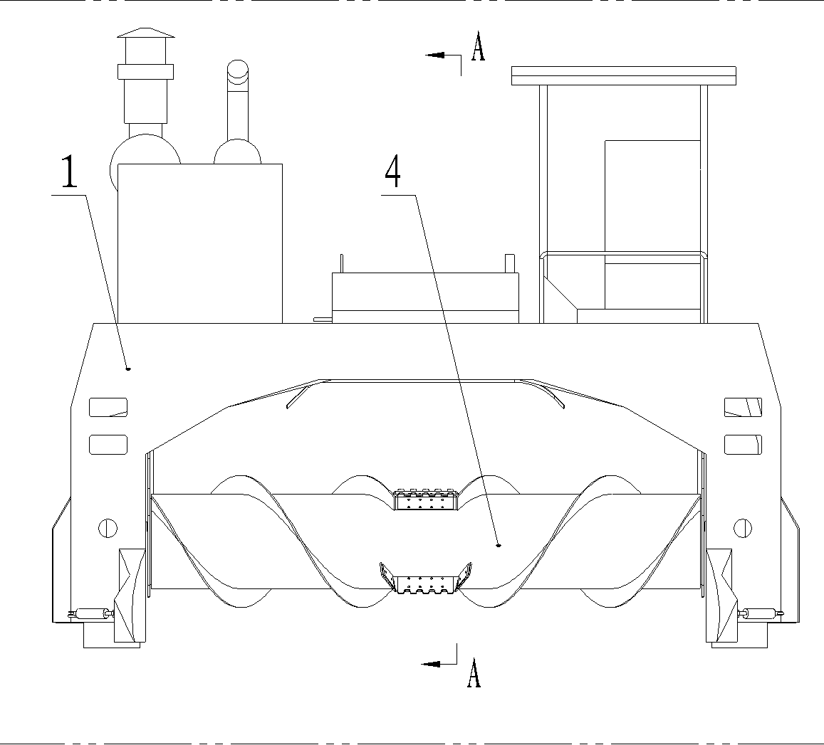
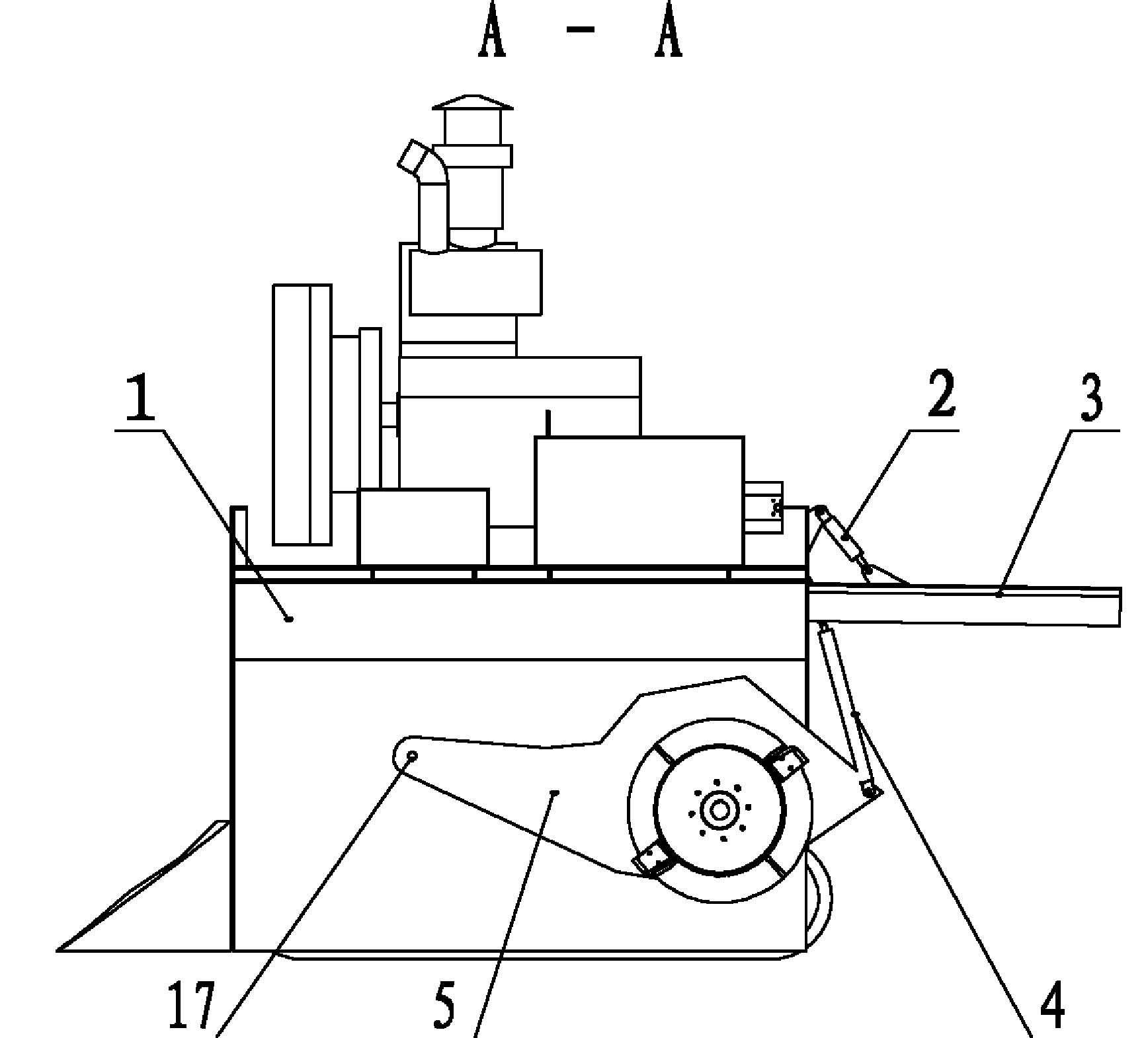
[0014] Such as figure 1 , figure 2 The shown fertilizer turning and throwing machine has a portal frame 1, a pair of rocking arms 5 are installed through the hinged shaft in the middle part below the portal frame 1, and the turning and throwing wheels are housed on the rocking arms 5, and the turning and throwing wheels are located on the portal machine. The rear end of the frame 1, the rocking arm 5 and the hinged shaft 17 of the door frame 1 are relatively in front of the turning wheel, and the rocking arm 5 is located between the rear part of the turning wheel 4 and the door frame 1 Connected with lifting cylinder 4. The rear end of the portal frame 1 is hinged with a material retaining plate 3, and the lifting cylinder 2 for adjusting the rotational angle of the material retaining plate 3 is housed between the portal frame 1 and the material r...


PUM


Abstract

The invention discloses a fertilizer turning and throwing machine, which relates to the technical field of agricultural machinery manufacture. The fertilizer turning and throwing machine comprises a gate-type rack and a turning and throwing wheel installed on the gate-type rack by a rocker arm and a hinged shaft, wherein a lift cylinder is installed between the rocker arm and the gate-type rack. The fertilizer turning and throwing machine is characterized in that the hinged shaft is positioned in front of the turning and throwing wheel; the turning and throwing wheel is arranged on the rear part below the gate-type rack and is installed on the rear part of the inner side of the gate-type rack; the hinged position of the lift cylinder and the rocker arm is positioned behind the turning and throwing wheel; a driving motor is sheathed in one end of the turning and throwing wheel; the rear end of the gate-type rack is hinged with a material baffle plate; and an elevation cylinder used for regulating the rotating angle of the material baffle plate is arranged between the gate-type rack and the material baffle plate. Compared with the prior art, the fertilizer turning and throwing machine is characterized in that the turning and throwing wheel of the fertilizer turning and throwing machine is positioned behind the gate-type rack, which is beneficial to backwards turning and throwing the fertilizer, and the splashing distance of the fertilizer can be controlled by regulating the material baffle plate via the elevation cylinder.

Description

technical field [0001] The invention relates to the technical field of agricultural machinery manufacturing, in particular to a machine for turning and throwing fertilizers. Background technique [0002] The invention patent of the Chinese patent "Full Hydraulic Fertilizer Turning Machine" (patent number: 200810196780.6) discloses a fully hydraulic fertilizer turning machine, which mainly includes crawler walking system, frame, engine, driver's cab, hydraulic system, and rotor lifting System, rotor system, walking hydraulic motor and rotor hydraulic motor. The crawler walking system has two sets, one on the left and one on the left, and the downward device is at the bottom of the frame. Both the rotor system and the driver's cab are installed on the top of the frame, the rotor system is connected between the left and right crawler belt travel systems, and connected with the rotor hydraulic motor, and the two ends of the rotor system are connected with the rotor lifting syst...

Claims


Application Information

Patent Timeline
Patent Type & Authority Applications(China)
IPC IPC(8): C05F17/02C05F9/04
CPCY02A40/20
Inventor 林家祥林家平许冠能岑林华冯活清
Owner GUANGXI UNIVERSITY OF TECHNOLOGY
Why Eureka
Try Eureka