
Quenching machine tool with rotary quenching mechanism

A technology of quenching machine tools and rotating mechanisms, applied in the field of quenching machine tools, can solve problems such as difficult to achieve, high precision, and high cost, and achieve the effects of low cost, simple mechanism, and simple structure

Active Publication Date: 2012-10-03
ZHENJIANG TIANXIANG PRECISION ELECTRIC MACHINERY
View PDF4 Cites 10 Cited by
  • Summary
  • Abstract
  • Description
  • Claims
  • Application Information

AI Technical Summary

Problems solved by technology

But there are the following disadvantages: 1. Due to the use of 6 axes, the errors on each axis are accumulated, and the errors are relatively large, and it is difficult to achieve high precision; 2. The structure of the mechanical arm is used, and the cost is relatively high

Method used


Image

  • Quenching machine tool with rotary quenching mechanism
  • Quenching machine tool with rotary quenching mechanism
  • Quenching machine tool with rotary quenching mechanism

Examples


Embodiment Construction

[0028] The present invention will be described in detail below in conjunction with accompanying drawing.

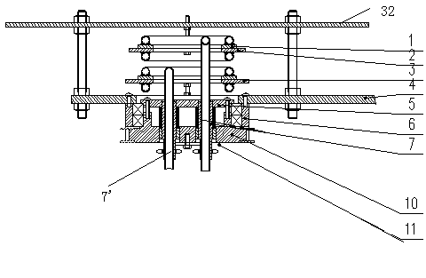
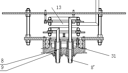
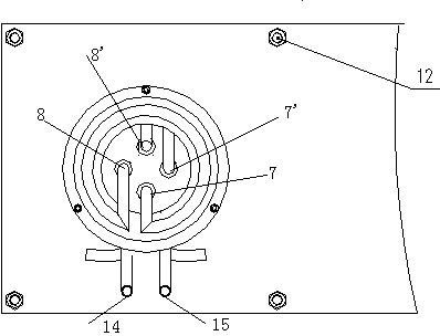
[0029] Such as figure 1 , figure 2 , image 3 As shown, the rotating mechanism 21 contains two rotating pairs 13, and each rotating pair 13 contains two turns of water pipes, and the two turns of water pipes are connected by the moving contact plate 1 and the static contact plates (2, 3). One of each rotating pair 13 One end of the circle water pipe is connected with a water inlet (14,15) protruding from the quenching transformer 23, and the other end is provided with a water outlet (17,18), and one end of another circle water pipe is connected with a water inlet of a moving touch panel, and the other One end is connected to an induction coil connector tube. The water pipe of the swivel pair that connects the water inlet (14,15) that stretches out in quenching transformer 23 li is positioned at the below of swivel pair 13. Such as Figure 4 Shown is a schematic diag...


PUM


Abstract

The invention relates to a machine tool, in particular to a quenching machine tool. The conventional quenching machine tool is high in cost and low in precision. The invention provides a quenching machine tool with a rotary quenching mechanism, wherein the rotary quenching mechanism is arranged n a cross beam (28) of the machine tool and can move leftwards and rightwards, up and down. The quenching machine tool is characterized in that a rotating mechanism (21) is arranged in the rotary quenching mechanism and between a quenching transformer (23) and a quenching coil (19); and the rotating mechanism (21) can allow the quenching coil (19) to randomly rotate. The mechanism is simple; the quenching mechanism is controlled to quench a quenched piece by leftward and rightward, up and down movement of the quenching mechanism and forward and backward movement of the machine tool; and because the movement is horizontal, a high precision can be achieved. The structure is simpler than a mechanism arm; and the transformer with low using cost and large size can be used in the mechanism, so that the cost of the whole mechanism is lower.

Description

technical field [0001] The invention relates to a machine tool, in particular to a quenching machine tool. Background technique [0002] Existing machine tool quenching, especially numerical control machine tool quenching, makes the quenched parts move at a certain speed through programming, and the quenching process needs to be carried out manually and through manual experience. Due to the use of manual work, the production efficiency is low, and the deformation and thermal influence of the workpiece after heating are relatively large. Since the quenching is based on manual experience, the processing quality is greatly affected by manual work, and the quality is difficult to maintain stable. [0003] The application number is 200910060896.1, and the patent application document named "Abrasive Tool Surface Induction Hardening Machine Tool" discloses a quenching machine tool, which can process any shape and various parts through a 6-axis mechanical arm. But there are the ...

Claims


Application Information

Patent Timeline
IPC IPC(8): C21D1/62C21D1/42C21D1/10
CPCY02P10/25
Inventor 赵天林高峰赵玉山
Owner ZHENJIANG TIANXIANG PRECISION ELECTRIC MACHINERY
Features
  • Generate Ideas
  • Intellectual Property
  • Life Sciences
  • Materials
  • Tech Scout
  • Unparalleled Data Quality
  • Higher Quality Content
  • 60% Fewer Hallucinations
Learn More