Cantilever crane device and engineering machinery

A technology of construction machinery and boom, which is applied in the field of boom devices and construction machinery containing the boom device, which can solve the problems of large start-up load, low sensitivity, and slow response speed of turntables, so as to achieve small impact on structural strength and reduce production. Cost, the effect of reducing bending wear

Active Publication Date: 2012-10-03
SANY AUTOMOBILE MFG CO LTD
View PDF17 Cites 2 Cited by
  • Summary
  • Abstract
  • Description
  • Claims
  • Application Information

AI Technical Summary

Problems solved by technology

Due to the large volume and weight of the boom device itself, this horizontal rotation method has a large inertia, which not only increases the energy consumption of the pump truck, but also has an adverse effect on the service life of the entire boom
[0004] Driving the turntable to rotate has the following disadvantages: the turntable has a large start-up load, high energy consumption, low sensitivity, and slow response speed; the center of gravity of the boom is easy to exceed the safe range
[0005] In the existing boom device, the relative movement between all the booms is limited to the rotation in the vertical plane, which limits the movement trajectory of the boom, affects the flexibility of the concrete pump truck, and has a dead point in the distribution, which affects the construction efficiency

Method used


Image

  • Cantilever crane device and engineering machinery
  • Cantilever crane device and engineering machinery
  • Cantilever crane device and engineering machinery

Examples


Embodiment Construction

[0033] In order to enable those skilled in the art to better understand the technical solutions of the present invention, the present invention will be further described in detail below in conjunction with the accompanying drawings and specific embodiments. It should be noted that, in the case of no conflict, the embodiments of the present application and the features in the embodiments can be combined with each other.

[0034] In the following description, many specific details are set forth in order to fully understand the present invention. However, the present invention can also be implemented in other ways than described here. Therefore, the protection scope of the present invention is not limited by the specific implementation disclosed below. Example limitations.

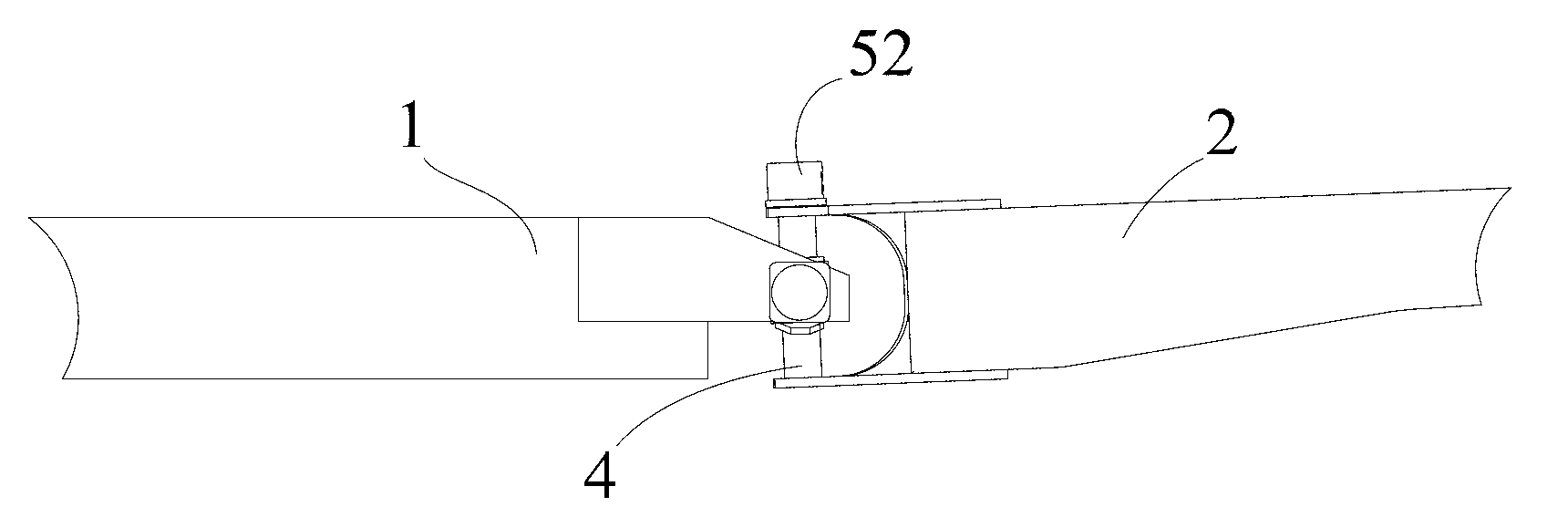
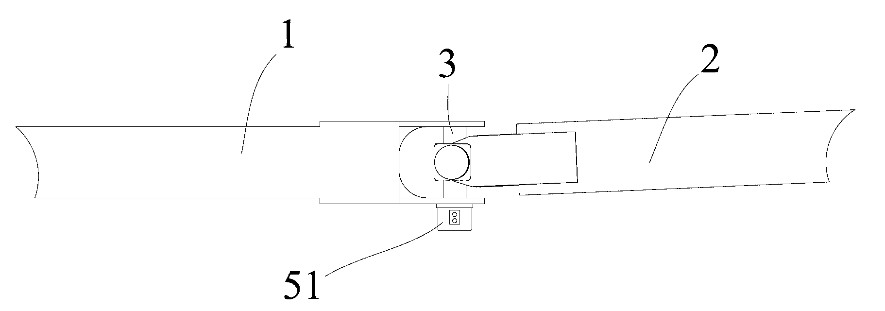
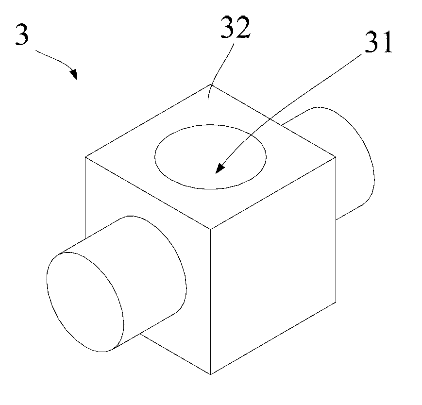
[0035] like Figure 1 to Figure 5 As shown, the present invention provides a boom device for construction machinery, including a first joint 1 and a second joint 2, and also includes a first coupling shaft 3...


PUM


Abstract

The invention provides a cantilever crane device used for engineering machinery, which comprises a first section of arm, a second section of arm, a first coupling shaft, a second coupling shaft, wherein the first coupling shaft and the second coupling shaft are fixedly crossed; the axes of the first coupling shaft and the second coupling shaft are vertical to each other; two ends of the first coupling shaft are respectively rotatably mounted on the first section of arm; the two ends of the second coupling shaft are respectively rotatably mounted on the second section of arm; a first driving mechanism is mounted on the first section of arm; the first driving mechanism can drive the first section of arm and the first coupling shaft to relatively rotate; a second driving mechanism is mounted on the second section of arm; and the second driving mechanism can drive the second section of arm and the second coupling shaft to relatively rotate. The invention also provides the engineering machinery. According to the technical scheme provided by the invention, a simulated universal joint driving mode is adopted; the structure is simple; a cantilever crane can swing along the vertical and / or horizontal direction; the flexibility in distributing materials is greatly increased; a turntable is not started when the cantilever crane device is rotated in a small scope; and the energy consumption is saved.

Description

technical field [0001] The invention relates to the field of construction machinery, and more specifically, to a boom device and construction machinery including the boom device. Background technique [0002] At present, a concrete pump truck generally includes a traveling device, a pumping device and a boom device. The walking device is mainly used for the transfer of the pump truck on the work site, and the pumping device and the boom device are mainly used for transporting concrete to the place where concrete is needed during the construction process. [0003] The boom device consists of multi-section booms hinged in turn, and the two adjacent booms mainly rotate in the vertical plane, and horizontal rotation cannot be realized; if horizontal rotation is required, the turntable can only be driven by the rotary motor and the reducer relative to the fixed The turret rotates, thereby realizing the horizontal rotation of the jib device. Due to the large volume and weight of...

Claims


Application Information

Patent Timeline
Patent Type & Authority Applications(China)
IPC IPC(8): E04G21/04
Inventor 涂星邓彪刘祥
Owner SANY AUTOMOBILE MFG CO LTD
Why Eureka
Try Eureka